This thread has been locked.

If you have a related question, please click the "Ask a related question" button in the top right corner. The newly created question will be automatically linked to this question.

TRF1208EVM: TRF1208EVM

Part Number: TRF1208EVM
Other Parts Discussed in Thread: TRF1208, ADC12QJ1600

Tool/software:

Dear Team,

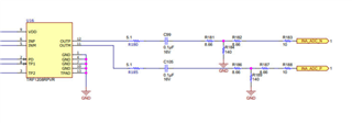
Could you please clarify whether the TRF1208EVM schematic has a mistake, as the attached image shows C71 and C63 as 0.1 nH. Similarly in the TRF1208PVR Datasheet (Table 8-2), inductor is used in place of Capacitors
Link for datasheet: www.ti.com/.../trf1208



Regards,
Liston

  • Hi there Liston,

    The schematic you shared is not for the TRF1208EVM. The TRF1208EVM only has the TRF1208 device and a few adjacent components on the board. Can you confirm which board you are looking at?

    Thanks,
    Gideon

  • Hi Gideon,

    I am trying to integrate ADC12QJ1600 with TRF1208.
    How to tune the RLC components so that the network is matched for ADC12QJ1600?

    Regards,
    Liston

  • Thanks for sharing the device name. The ADC12QJ1600 is a buffered input ADC, so the input return loss should be pretty good. This means that after matching the output of the TRF1208 to 100 ohms differential in your pass band, the ADC should behave as expected with the TRF1208.

    The TRF1208 is a low output impedance amplifier, and so some matching is needed here to give the anticipated response. On wideband matches, typically a 3 to 5 dB resistive Pi or T attenuator is used directly after the TRF1208 to bring the output impedance to 100 ohms differential, which then can be followed with two 50 ohm single ended filters, or a 100 ohm differential filter to give the appropriate response. This approach is seen in the TRF1208-ADC12DJ5200EVM, schematic seen below.

    In the above, R181,R182,R184 make up one resistive attenuator on the OUTP output, and R186, R187,R189 make up the other on the OUTM output of the TRF1208. These resistive attenuators are located physically close to the output of the TRF1208. The value of these attenuators is 3 dB in this case. The higher the attenuation, the more loss, but the better match. Then there is a distance along the board using 100 ohm differential transmission lines into two 10 ohm resistors and the ADC itself.

    This EVM shows a wideband approach to the matching. If some filtering is required, filters would be placed directly after the resistive attenuators and be either 2 single ended 50 ohm filters, or 100 ohm differential filter.

    In narrowband approaches, resonant matching can be used, but this is more difficult to achieve. You can get less loss with this approach, but there is more difficulty in design and harder to predict response due to board parasitics playing a bigger part.

    Let me know if any other questions come up,
    Gideon