This thread has been locked.

If you have a related question, please click the "Ask a related question" button in the top right corner. The newly created question will be automatically linked to this question.

ADS1291: ADS1291

Part Number: ADS1291
Other Parts Discussed in Thread: ADS1298

Tool/software:

Hi Team,

We are using ADS191 device. While reviewing the reference design for ADS1298, I noticed that it incorporates two-stage RC filters, with cutoff frequencies of 153.225 kHz and 338.627 kHz. My question is: since the frequency of the ECG signal falls between 0.05 Hz and 150 Hz, why are these cutoff frequencies set so high? Is there a specific reason for implementing this in the development kit?


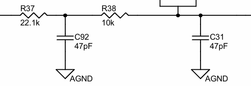
I have another question regarding the RLD non-inverting amplifier. In the development kit, the gain is set to unity. Can we increase the gain of this amplifier to further reduce common mode noise? I understand the importance of amplifier stability, but considering stability, could we still increase the gain to help minimize common mode noise?
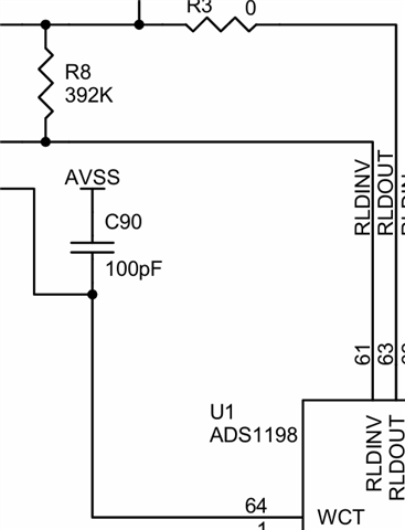


Thanks, and Regards
Karthik P R

  • Hello Karthik,

    The LPF filter in the ADS1298EVM is set up as an anti-aliasing filter, which does not need to be in the bandwidth of interest. Additionally, using larger value components has the potential to introduce more common-mode noise to the system, since the varying tolerances of these components affect the total noise on the line.

    The RLD non-inverting amplifier is designed to drive a waveform that is equal and opposite to the common mode noise detected on the other electrodes in order to cancel it out. Increasing the gain of the RLD amplifier will not reduce the common mode noise, since it will no longer be equal to the common mode signal on the other inputs.

    Regards,

    Payton

  • Hello Karthik,

    As a minor correction to my previous answer, the RLD amplifier gain is not unity, and you can change the gain of the RLD amplifier circuit by changing R8 manually. You can see how the gain is calculated here: How do I calculate the DC gain of the RLD or BIAS amplifier?

  • Hi Payton,

    Thanks for your prompt reply. You mentioned that the anti-aliasing filter does not need to be within the bandwidth of interest. Suppose my signal of interest is at 500Hz or 1000Hz, meaning my sampling frequency would be 2kHz. If I set the filter cutoff frequency much higher, such as 156kHz, wouldn’t high-frequency signals alias with my signal? In that case, I would need to prevent aliasing, correct?

    When you said the anti-aliasing filter does not need to be within the bandwidth of interest, does this mean the AFE chip itself takes care of aliasing? Could you please clarify?

    I understand that lowering the cutoff frequency may require larger component values, which could introduce thermal noise.

    Thanks and Regards
    Karthik P R
  • Hi Karthik,

    The external anti-aliasing filter is designed to attenuate aliasing from the modulator frequency, not the sampling frequency, since the signal noise at the sampling frequency is already filtered by the digital sinc filter in the passband. You can see how the passband aliases at every multiple of the modulator frequency in Figure 56 below.

    The anti-aliasing filter cutoff frequency should be much higher than the signal bandwidth to ensure that the filter doesn't attenuate any of the signal within the bandwidth of interest (because even if the sampling frequency is less than the anti-aliasing cutoff frequency, if it's too close, some signal attenuation will still occur). The modulator frequency for the ADS1298 is typically 512kHz (fclk/4) in high-power mode, and 256kHz (fclk/8) in low-power mode, so those are the frequencies that need to be attenuated by the anti-aliasing filters.

    Regards,

    Payton