Tool/software:
Hello
We are using the ADC chip ADS8688 in our measuring device.
When I read out the eight channels I get always the same value back. After a power cycle of the ADC the value may change, but with a reset (HW or SW) the value remains.
Before reading the the single channel I a doing an initialization section where the range register are set and read back. This works fine. Any value is set to the configuration register I can read back afterwards.
I tried to used AUTO-REST mode and MANUAL mode. But with no difference.
The flow is like:
- RESET ADC (0x8500)
- Delay 10ms
- AUTO-RST (0xA000)
- Set register CHANNEL_PWR_DWN to 0x00
- Set register INPUT_RANG for channel 0 to 7 to Bidirectional 5.12V (0x01)
- Read back configuration registers and check if set correct
- If not correct reset ADC and redo the configuration several times finally we land in hard fault error handler
- If correct carry on
- NOP (0x0000) <- to bring ADC back into IDLE state
- Read ADC channels 0 to 7 in a loop with AUTO-RST or MANUAL read command
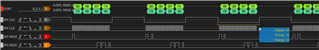
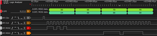
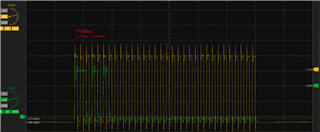
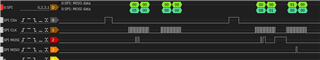
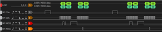
Configuratins section on the SPI Bus: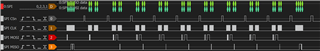
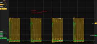
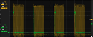
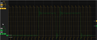
DAQ Section: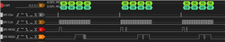

Detail view: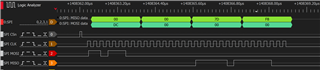
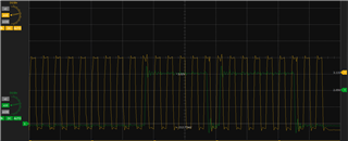
Whole view: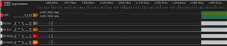
Schematic: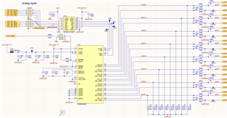
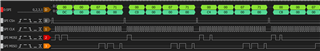
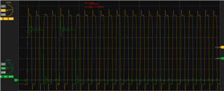
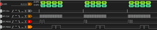
I also tried to do frequently a reset, in the hope the ADC . In this example a reset command (0x8500) is send after 16 channel reads (2x 0 to 7) with AUTO-RST command: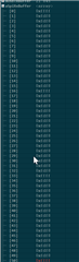
The reset command is executed successful, so the first value after a reset is 0xffff (invalid) and the next 15 conversation have all the same value.
It would be nice if your HW is that noise resistant, that not even a bit flickers, but that's not the case. I can even shorten AIN_p and ANI_n to GND and the constant values remain.
I am very happy for any idea to solve the issue.
Many thanks'
Simon