This thread has been locked.

If you have a related question, please click the "Ask a related question" button in the top right corner. The newly created question will be automatically linked to this question.

ADS1256: ADS1256 ADC Circuit Design Review - 0.1-20 Hz Signal Sampling at 100 SPS

Other Parts Discussed in Thread: NE5532, ADS1256, OPA735, LM27762

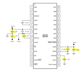
I designed a circuit using the ADS1256 24-bit ADC, using NE5532 op-amps for signal conditioning and an LM1117MP voltage regulator. I will add the filtering circuit later. Could you please review this schematic and provide feedback on possible issues or improvements? The data I will be converting is between 0.1-20 Hz and I will be sampling at 100 samples per second.

  • Hi Hüseyin Yalçin,

    Your schematic did not post correctly. Can you select "Insert->Image/video/file" from the menu below?

    Then hit the "upload" link, even though it is grayed out. This will allow you to upload a file

    Also, is there any reason you are using very old devices for your application? The regulator and ADC are from ~2000, while the op amp is from 1979. Are you interested in more modern technology?

    -Bryan

  • I have taken your suggestions into account and tried to use more up-to-date components

  • Hi Hüseyin Yalçin,

    Many of your cap values are incorrect, see the recommendations from the datasheet as shown below

    The OPA735 looks like it has +5V nets on both supplies, which obviously will not work.

    Why not use something like LM27762: this devices takes a single supply voltage and generates a stepped down, clean bipolar output. So for example you can apply 5V to VIN and then get +/-2.5V on the output. This makes the most since because you will already have to generate a bipolar supply for the OPA735 in your existing circuit. Why not just remove the REF + buffer + inverting amp and just use a single, simple device to generate your supplies?

    -Bryan