This thread has been locked.

If you have a related question, please click the "Ask a related question" button in the top right corner. The newly created question will be automatically linked to this question.

ADS1261: Responding with All Zeros Part 2

Part Number: ADS1261

Tool/software:

The original thread for this problem was closed as resolved but it is not resolved. 

The original problem is that the TI-ADS1261 does not respond in the DOUT line to commands sent to it on the DIN from a Xilinx Zynq 7020 SPI bus. The 1261 is inconsistent in responding to the RESET command which typically fails with silence on DOUT, then after approximately forty attempts the 1261 begins to respond to RESET 0x06, 0xFF with DOUT 0xFF, 0x06. But as soon as the 1261 gets a RREG command using the same bus and same software it stops responding entirely.

Currently I have many of the individual commands working dependably for multiple tests in a row including NOP, RESET, LOCK, UNLOCK.

However, as soon as I attempt to do a RREG command it succeeds for one RREG command then all responses stop from the 1261 including RESET which previously worked. This is true after the RREG no matter how many times I do the RESET. The only way to get the 1261 working again after RREG is a power cycle.

Another thing I’ve noticed that I need to fix somehow is that after power up it takes somewhere between 25 and 100 RESET commands sent to the 1261 before it starts responding. I am not doing anything differently for any command.

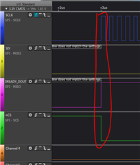
The first diagram below shows a series of spikes which are all good reset commands with responses and which were reported as successful by the software. The second diagram shows a clock level view of the very first reset spike at the clock level. And the third shows a clock level view of the RESET after RREG which is one of hundreds after the 1261 stops responding after the RREG command.

As you can see from the second diagram my clock settings now look pretty good. The bus clock turns on during transmit and receive and afterwords goes low. It is clear in the diagram that the DIN into the 1261 latches on the clock rising edge so it provides a stable read on the falling edge and the 1261 DOUT looks like it is latching on the clock falling edge, as I think you indicated above.

I also include my full software log file this time. There is nothing proprietary in this file. The log file shows approximately 40 reset command fails until it starts working at line 454 followed by eight successful resets. Then I switch to the commands and the first RREG command is successful at line 483. After that the 1261 does not respond to anything. Keep in mind my software is exactly the same for the pass and fail RESET and RREG.

I need help uncovering the reason that the 1261 would delay responding to RESET as well as the reason why it would stop responding after getting the RREG command?

log 0005 sagrad spi ti ads 1261.txt

  • HI Everett,

    Is CS tied low in your system? At least in the first image CS is low the entire time (~1sec). When CS is tied low, the SPI communication is not reset as it would be if you framed your commands with CS high-low and then low-high transitions i.e. only pulling CS low during the duration of the frame while meeting all other timing requirements. If there are any errant glitches or anything like that on SCLK, the ADC might interpret these as valid SCLK pulses and get out of sync. This could explain why your first command is good and then everything gets messed up after that. And then after dozens of tries another command works

    There is no other obvious reason why the communication would be this sporadic, unless of course the ADC has been damaged

    -Bryan

  • Bryan, 

    I thought we had the CS tied correctly to the chip select output of the Xilinx SPI bus so that when I write the slave select to the Xilinx SPI configuration register and it selects the slave it raises the CS on the correct slave. But obviously this is not the case since apparently the CS line is not moving. I will check all previous plots to see if CS was at one point moving. Maybe I changed something in the Xilinx SPI bus configuration registers which broke it and it is no longer driving CS. Or maybe as you say, it is indeed tied low, I will check with HW.

    I agree with you that failing to drive CS correctly may be the cause of the problem. I am curious why some commands work consistently for multiple commands in a row and some do not work at all. But perhaps that is a distraction to solving the problem if CS is the root cause.

    We are re-spinning the board soon and in the next revision I will be given directly control over the CS line. I've tried everything I can think of in the software at this point. So let's close this issue for now! I don't think it will be beneficial to spend any more time on it until CS is driven correctly. Hopefully that will solve the issue. If not then we will have to choose a different TI-ADC since we can't change the processor SOC. 

    Many thanks for your help and quick responses.

  • HI Everett,

    I would also recommend getting an EVM. This will establish an operational baseline that you can benchmark against what your controller is doing. You can also verify your HW with our controller / GUI (by fly wiring them together) to make sure there are no HW issues either (so far we have assumed this is purely a software / communication issue)

    The ADS1261 is more than capable of operating using a standard SPI interface, as are most of our other precision ADCs. But they all communicate roughly the same way, so it is possible that if this is a comms issue, choosing a new ADC will not resolve it.

    -Bryan

  • I got chip select to work but when chip select is working the 1261 does not echo the command. The following graphs demonstrate this.

    By comparison, this is my software version 337 in which I was able to get the reset command to respond DIN 0x06, 0xFF DOUT 0xFF, 0x06, and other single commands work but RREG, WREG and RDATA do not reply. The graph shows the correct response on DOUT without any action on CS.

    The next graph is from my most recent software 346 which shows a good SCLK, DIN, CS but DOUT goes high and stays high thus not responding to the reset 0x06, 0xFF.

    This graph is also for software 346 CS is wider and does not exactly match the clock, I don't know why this changed, DOUT mirrors CS and does not respond to the command.

    This is a magnify of the same capture showing more detail in the clock which looks good to me and a good reset on DIN (SPI BUS MOSI) 0x06, 0xFF but nothing on 1261 DOUT.

    I also tried hardware reset on the 1261 RESET pin before every command but this had negative impact. I also tried cycling through all bus slave channels, 0, 1, 2 and I got a few reset commands to go through but then it stopped working and refused to start working again.

    At this point I have one software version with limited success, 337, which fortunately is checked into GIT, which will send about 100 failed reset commands before the 1261 starts responding correctly to them with good reset echo on DOUT and then it will respond to individual commands such as NOP, START, STOP LOCK, UNLOCK. But as soon as it gets a RREG command it stops communicating and will no longer work even on the RESET command which previously worked.

    I think your suggestion about getting Chip Select programmed properly was a good one but functionally it actually made it worse. On that software build 1261 did not respond at all even though CS does what it should in relation to CLK. I suspect CS should be tied active low because that is what it looks like when it works.

    I am confident my clock polarity is correct because the only way I could get it to respond at all was for the SPI BUS to latch on the clock leading edge so the 1261 can sample on a stable falling edge as I think you mentioned above. 

    What is mystifying to me is that even when CLK and DIN are run perfectly the 1261 simply refuses to respond.

    At this point there is nothing else I can try in the software. And unless you can think of some way to get the 1261 to talk I will wait until we get our development board before proceeding. Sincere thanks for your time on this.

    Everett

  • HI Everett,

    For sure there are timing delays between CS low and SCLK high, check the timing requirements of the ADS1261 datasheet i.e. this is not allowed:

    Add a delay of one SCLK (200ns for example) between CS low and SCLK high and see if that improves the situation. Do the same on the back end (SCLK low to CS high)

    It also looks like your LA is still triggering on the rising edge based on the icon you have selected in the top left corner. This needs to trigger on the falling edge (the data looks okay, so your system might be getting the correct data, only the LA is wrong)

    Also the third and fourth images are showing that CS is high when you are sending SCLKs, which means the ADC is not receiving them. So of course the ADC will not respond.

    -Bryan

  • OK, I will see if I can drive CS low a little earlier than the clock start. There is no setting to my knowledge of a lead time in the SPI Bus registers but I think I can do that by trying manual slave select mode and selecting the slave then waiting for a delay before enabling the clock and then doing the transmit. That should work.

    You're right. If CS is high there is no chance it will respond. I do have some old plots though of no response while CS is low. I think that was for the RREG command. 

    Based on all the testing we have done I'm coming around to the idea that there is most likely nothing wrong with the 1261 and I don't have the SPI Bus programmed correctly. However, if we could leave this thread open for another day or two I would like to post plots of the results of adjusting the CS lead time per your suggestion. I should have them by end of day today.

    Thanks!

    Everett

  • Hi Everett,

    Understood

    Sometimes it is possible to use your SPI peripheral in 3-wire mode, then use a GPIO to control CS. Then you have more control over the CS pin timing. Not sure if this is an option on your controller, this is just a general observation

    Let me know if you make any progress

    -Bryan

  • My thoughts exactly. I already made plans with our hardware lead on the upcoming re-spin to give me pin control of CS, START, RESET. I'm implementing your idea in the SW now, will post diagrams later today or AM tomorrow. As always, thanks!.

    Everett