This thread has been locked.

If you have a related question, please click the "Ask a related question" button in the top right corner. The newly created question will be automatically linked to this question.

ADS7028: Read and Write Issue with ADS7028

Part Number: ADS7028
Other Parts Discussed in Thread: TMS320F28377D

Tool/software:

Hello,

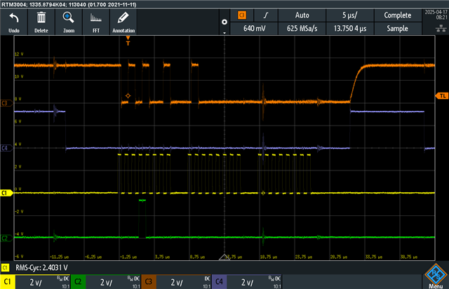
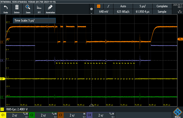
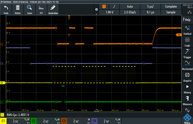
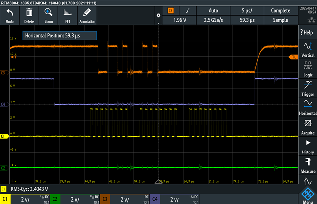
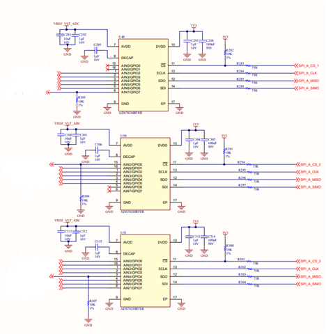
We are trying to use ADS7028 sensors for ADC readings in our project. But we are having issues with the communication. In short, we can't seem to write anything to the registers of the ADS7028 and when we read back the register contents of the same register for debugging, the content constantly keeps changing. This can be seen from the attached pictures. 

In these pictures, a register read command is sent for the SYSTEM STATUS REGISTER. But as it can be seen from the picture, the data received from the ADS7028 changes for each message. 


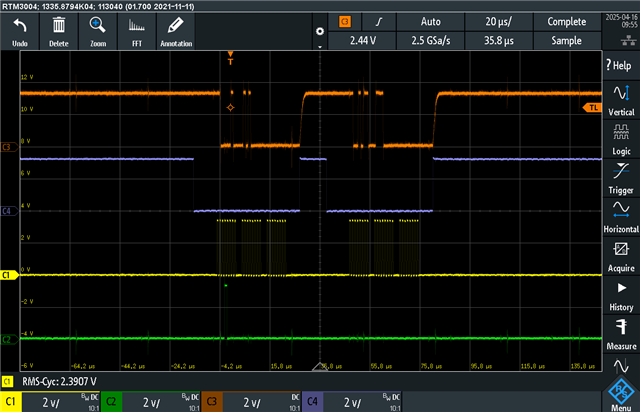
Orange: Data from ADS7028

Blue: Chip Select

Yellow: SCLK

Green: Data from MCU

We are really stuck, so any help is appreciated.

Thanks, regards.

  • Hi Ege,

    Thanks for reaching out. Are you able to send some more zoomed in pictures of the communication, and see the SCLK transitions clearly? Alternatively, a logic analyzer capture would also be best if you have one available.

    One thing I am noticing however is that the rise time of the ADS7028 SDO is fairly slow after ~CS goes high. This alone might not be the issue, but can you share a schematic or the pull-up resistor value you have on this line? 

    Regards,
    Joel

  • Hey Joel, 

    To zoom in more, I divided them both into two parts. One for read register command and one for the result. They might be a little different than old pictures, it is acting strange as I said. And this is the most I can zoom in, more than that and the data won't fit into the screen.

    First query:

    Second query:

    The coming data part is just acting strangely. I am not sure if we have a logic analyzer though.

    For the rise time of SDO, I implemented delays in us between chip select toggles to make sure that the device can acquire what is going on. I believe they are 5 us before and after the chip select toggle. For pull-ups we have 10 kohm resistors on chip select lanes.

    The schematic of ADS7028s:

    I had to omit left-side due to confidentiality but if there is not a cross they are connected. 

    Thanks, regards.

  • Hi Ege,

    It seems like your SPI mode configuration is incorrect on your controller. By default, the ADS7028 operates in SPI Mode 0 (CPHA = 0, CPOL = 0), where SCLK idles low while ~CS is inactive, and data is captured on the leading edge (rising edge in this case). So the ADS7028 device reads in SDI data from the controller on SCLK rising edges. Because of this, a certain setup time is necessary to ensure SDI is stable before the rising edge of SCLK, and so data for the next rising edge of SCLK is usually changed on the previous SCLK falling edge.

    At the moment, it looks like SDI changes at the same time as the SCLK rising edge, so the setup time is being violated. This should be relatively easy to change. This should fix your issues assuming everything else is correct. Let me know if you have any additional trouble.

    Regards,
    Joel

  • Hey Joel, surprisingly that actually fixed it. 

    The surprising part is my MCU is TMS320F28377D and initialization code was the following:

    // Initialize SPI-A
    // Set reset low before configuration changes
    SpiaRegs.SPICCR.bit.SPISWRESET = 0;
    // Enable master (0 == slave, 1 == master)
    SpiaRegs.SPICTL.bit.MASTER_SLAVE = 1;
    // Clock polarity (0 == rising, 1 == falling)
    SpiaRegs.SPICCR.bit.CLKPOLARITY = 0;
    // No loopback
    SpiaRegs.SPICCR.bit.SPILBK = 0;
    // Clock phase (0 == normal, 1 == delayed)
    SpiaRegs.SPICTL.bit.CLK_PHASE = 0;
    // Set the baud rate (SPI Baud = LSPCLK / (BRR + 1))
    SpiaRegs.SPIBRR.bit.SPI_BIT_RATE = 49; // (1 MHz)
    // No high speed mode.
    SpiaRegs.SPICCR.bit.HS_MODE = 0;
    // 8-bit character
    SpiaRegs.SPICCR.bit.SPICHAR = 0x07;
    // Clear SPI flags
    SpiaRegs.SPISTS.bit.OVERRUN_FLAG = 1;


    // Initialize SPI-A FIFO registers
    // Enable FIFO
    SpiaRegs.SPIFFTX.bit.SPIFFENA = 0;
    // Clear FIFO flags
    SpiaRegs.SPIFFTX.bit.TXFFINTCLR = 1;
    SpiaRegs.SPIFFRX.bit.RXFFOVFCLR = 1;
    SpiaRegs.SPIFFRX.bit.RXFFINTCLR = 1;
    // Release FIFOs from reset
    SpiaRegs.SPIFFTX.bit.TXFIFO = 1;
    SpiaRegs.SPIFFRX.bit.RXFIFORESET = 1;
    // Set levels for interrupts, interrupts will not be used
    SpiaRegs.SPIFFRX.bit.RXFFIL = 1;
    SpiaRegs.SPIFFRX.bit.RXFFIENA = 0;

    And this did not work. It normally should have initialized SPI with CLKPHA and CLKPOL 0. But when I changed the phase to 1 like the following, it somehow fixed the issue:

    // Initialize SPI-A
    // Set reset low before configuration changes
    SpiaRegs.SPICCR.bit.SPISWRESET = 0;
    // Enable master (0 == slave, 1 == master)
    SpiaRegs.SPICTL.bit.MASTER_SLAVE = 1;
    // Clock polarity (0 == rising, 1 == falling)
    SpiaRegs.SPICCR.bit.CLKPOLARITY = 0;
    // No loopback
    SpiaRegs.SPICCR.bit.SPILBK = 0;
    // Clock phase (0 == normal, 1 == delayed)
    SpiaRegs.SPICTL.bit.CLK_PHASE = 1;
    // Set the baud rate (SPI Baud = LSPCLK / (BRR + 1))
    SpiaRegs.SPIBRR.bit.SPI_BIT_RATE = 49; // (1 MHz)
    // No high speed mode.
    SpiaRegs.SPICCR.bit.HS_MODE = 0;
    // 8-bit character
    SpiaRegs.SPICCR.bit.SPICHAR = 0x07;
    // Clear SPI flags
    SpiaRegs.SPISTS.bit.OVERRUN_FLAG = 1;


    // Initialize SPI-A FIFO registers
    // Enable FIFO
    SpiaRegs.SPIFFTX.bit.SPIFFENA = 0;
    // Clear FIFO flags
    SpiaRegs.SPIFFTX.bit.TXFFINTCLR = 1;
    SpiaRegs.SPIFFRX.bit.RXFFOVFCLR = 1;
    SpiaRegs.SPIFFRX.bit.RXFFINTCLR = 1;
    // Release FIFOs from reset
    SpiaRegs.SPIFFTX.bit.TXFIFO = 1;
    SpiaRegs.SPIFFRX.bit.RXFIFORESET = 1;
    // Set levels for interrupts, interrupts will not be used
    SpiaRegs.SPIFFRX.bit.RXFFIL = 1;
    SpiaRegs.SPIFFRX.bit.RXFFIENA = 0;

    No idea why though. If you have any ideas why this happened, I would appreciate it. 

    Thanks, regards.

    Ege