This thread has been locked.

If you have a related question, please click the "Ask a related question" button in the top right corner. The newly created question will be automatically linked to this question.

ADS1291: It's unclear exactly what passives are required on the input side into INP/INN

Part Number: ADS1291
Other Parts Discussed in Thread: ADS1292R,

Tool/software:

I see on the layout examples and the development kit that there are many passives on the input lines

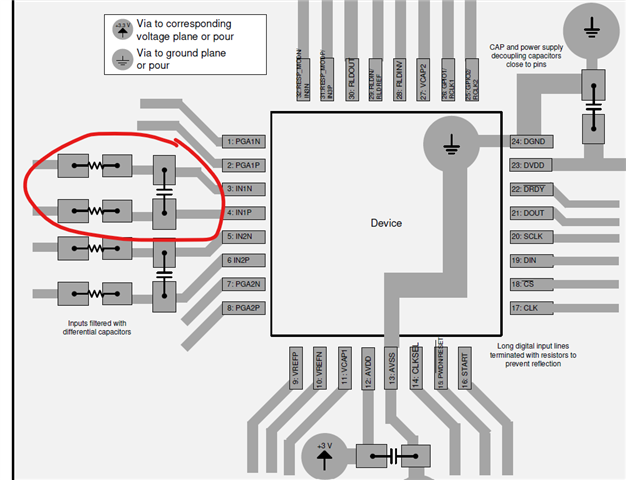
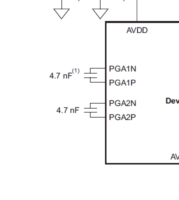
 It looks to me like just a 4.7 nf is required and its suggesting some patient protecting resistors, is that correct?

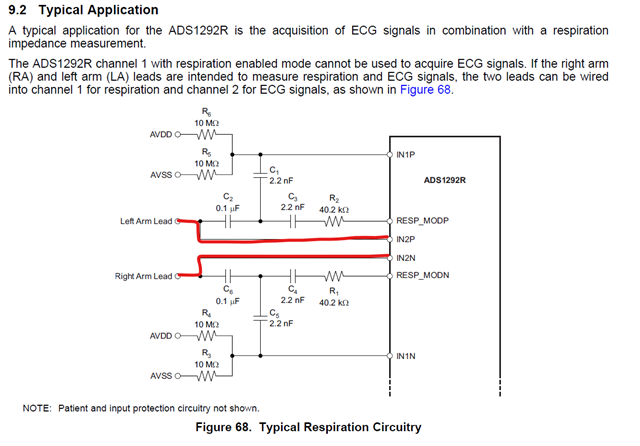
When i see the typical application it has an example with no passives if not using the respiratory functions. Is this example only relating to respiration?

Now when i look at the development kit im a bit taken back.

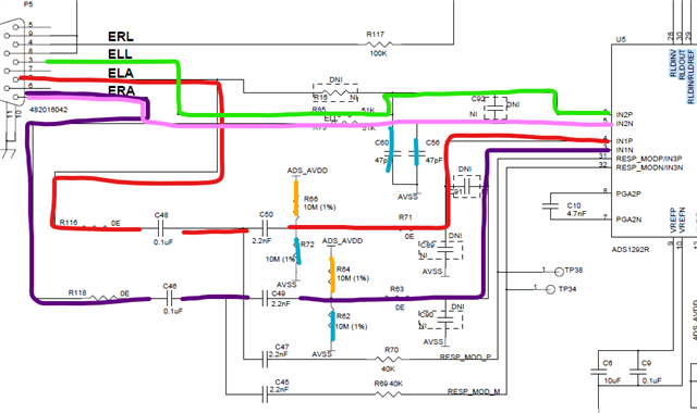
Out of these options, assuming i just want to use 2 electrode, one lead eeg.  On my design i am just using IN1P and IN1N including the 4.7nf cap.   

On the development kit i have been using ERA and ELA but this doesnt seem to match with what i intend to do.
It looks like I should be using ELL and ERA but on the development software my options are ● ECG Lead I
● ECG Lead II
● ECG Lead III
● ECG Lead aVR
● ECG Lead aVL
● ECG Lead aVF

I'm a bit confused reading through the documentation how these map to IN1P and IN1N.

Any help is appreciated.

  • Hi Kyle,

    Thank you for your post.

    The ADS1292R is marketed primarily for ECG applications, either for 2 ECG channels, or for 1 ECG channel and 1 Respiration channel. Of course, any bio-potential signal can be measured by the same IC (provided the SNR is sufficient), but the suggested signal chain components and how they map from electrode input to INxP/N pin is done with ECG and respiration measurements in mind. 

    The channel 1 circuitry on the EVM is designed as the respiration receiver channel. Since you only need to evaluate one EEG channel, I would suggest only using channel 2. This channel is DC coupled and only uses a first-order antialiasing filter in the path. By default, IN2P maps to P5.3 ("ELL") and IN2N maps to P5.1 ("ERA"). In the GUI, use the Scope, Histogram, and FFT tabs to analyze the data.

    The 4.7-nF caps between PGAxP and PGAxN are additional anti-aliasing at the output of the internal gain stage. This is detailed in the ADS1292R datasheet.

    Regards,

    Ryan

  • ah thank you. that is helpful. I am only using the ADS1291 and not the R, I had searched for an evaluation board and the only one available to me at the time was this unit which sounds like it does all configurations.

    you would suggest that the realtime continuous page isn't what i should be using?

  • Hi Kyle,

    You are correct that we only offer the evaluation module for the full version (ADS1292R). You can assume that the "ECG" performance of Channel 2 on the EVM would be equivalent to Channel 1 on an ADS1291 device.

    Correct - the "ECG \ RESP Display" tab assumes you have configured ECG electrodes as denoted on the User Guide. It then calculates the ECG leads and plots them accordingly. The simplest way to evaluate a single EEG channel would be to connect your electrodes as needed and view the Channel 2 results on the other 3 analysis tabs.

    Regards,

    Ryan

  • thank you for the info! very helpful.

    Maybe i am misunderstanding something but what is the difference between the ECG live display and the EEG analysis? should it not be the same? or is it filtered for typical cardiac signals with notch/bandpass filters?

  • The "Live ECG \ Resp Display" tab continuously acquires data and tracks the R-R interval to calculate heart rate for ECG leads. When Respiration data is displayed, it calculates the respiration rate. It also has the option to limit the signal bandwidth and implement a notch filter.

    The live stream data is handled differently in the GUI than the one-time acquisition of n samples using the Analysis tab. Under the Analysis tab, the acquired data set is available under each of the analysis tools. You can also export the data in Volts or Codes.

    My recommendation to use the Scope, Histogram, and FFT tabs was simply to avoid the confusion of mapping ECG naming conventions to the signals you wish to measure for your evaluation. For example, "CH1" would be more intuitive than reading "Lead II" and figuring out which ADC channel and which pins on the P5 DB9 connector they refer to.

    Regards,

    Ryan