This thread has been locked.

If you have a related question, please click the "Ask a related question" button in the top right corner. The newly created question will be automatically linked to this question.

DAC80516EVM: I2C protocol not reaching

Part Number: DAC80516EVM
Other Parts Discussed in Thread: DAC80516,

Tool/software:

Hi there,

I recently acquired the DAC80516 Evaluation Board and am currently trying to communicate with it. As an initial attempt, I tried using the GUI for High and Low-level configurations, but I didn’t get any noticeable results.

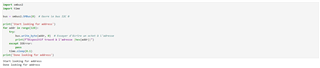
I then decided to use an I2C ID scan, which I had used previously to test other chips (it worked for them), directly on the accessible pins of the board (J15).

All jumpers are in the default configuration except for the following:

  • J16 – disconnected (to disconnect FTDI from the bus)

  • J17 – disconnected (to disconnect FTDI from the bus)

  • J18 – I2C-A0 = GND

  • J19 – I2C-A0 = GND

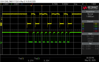
I then tried testing some power supply values, but nothing changed. I can observe the two-wire bus on the oscilloscope, but I never get the scan to return the expected 0x50 ID.

Thank you in advance for your assistance.

Best regards,
Jean

  • Hi Jean,

    Could you confirm the VIO and VDD voltage you are using on the board? Are you using the USB power or off-board power? From your jumper orientation, it does look like you should be able to communicate. 

    Thanks,
    Erin

  • Hi Erin,

    For the VIO, I always connected it to VDD. As for VDD, I tried both 5.5V and 3.3V. I'm only using USB power. I also checked that every test pin is at the correct voltage.

    By the way, I didn't verify whether the FTDI provides correct I2C communication, as I directly attempted to communicate with the DAC via I2C myself (though this doesn't affect the current issue).

    Thanks,
    Jean

  • Hi Jean,

    Some other questions. As the I2C bus is open drain, it requires pullups. Does your solution have pullups in place? If not, the pullups for the I2C bus on the EVM are actually on the FTDI side of J16 and J17. You could try populating J16 and J17 for I2C mode and put a jumper on J1. J1 will disable the voltage level shifter, so it will isolate your I2C from the FTDI. Also check to make sure your I2C voltage is equal to your VIO voltage. If that still doesn't work, it would be helpful to see the I2C signal you are sending to the device so I can confirm the signal is correct.

    Thanks,
    Erin

  • Hi Erin,

    I'm currently using a RedPitaya that provides two 3.3V I2C signals. I tried your suggestion by connecting J16, J17, and J1. Additionally, I set jumpers J5 to 1&2 and J6 to 3&4, so that VIO is tied to VDD, both at 3.3V. All VIO lines and my I2C signals are therefore operating at 3.3V.

    The way I'm testing the I2C communication is with the following approach: I run a try/except loop to scan all possible addresses and print out any that do not raise an error.

    Attached are pictures of my code and the oscilloscope results.

    Python I2C generation code

    Oscilloscope screen

    Thanks for your help,
    Jean

  • Hi Jean,

    So your program goes through addresses 0 to 128? It should definitely catch something then. I don't see anything wrong with your sequence either, which is unsurprising since you said it works for other devices. Perhaps you can try lowering the I2C speed? 1MHz is the upper end of the device's range - so maybe you'll have better results with a lower speed.

    Thanks,
    Erin

  • Hi Erin,

    Exactly, I’m scanning addresses from 0 to 128 to catch all possible I2C addresses.
    As for the clock speed, it's currently set between 350 and 400 kHz, which should be low enough, I believe.

    In the past, I’ve encountered chips that didn’t respond because they were in sleep mode, requiring a special pin to be pulled high or low to wake them up.
    Is there anything like that with this DAC? I don’t think so, but I also don’t see any other clues at the moment.

    Thanks,
    Jean

  • Hi Jean,

    The device has a Reset pin, but on the EVM this should be pulled high. Out of curiosity, could you try communicating with the device through the EVM GUI? It would be good to confirm that the device is working.

    Thanks,
    Erin

  • Hi Erin,

    Yes, I initially tried using the GUI, but since it didn’t work, I then used my personal I2C address analyzer. The GUI issue might be related to the device or to my current drivers. My computer seems to have a lot of trouble with them. It’s a recent model, but ever since I installed the DAC805xEVM software, it takes exactly 90 minutes to reboot. By the way, is this a common issue that other users experience?

    Thanks,
    Jean

  • Hi Jean,

    No, 90 minutes is very strange! Are you able to uninstall the GUI and see if the reboot goes back to normal? Could something have gone wrong with the install and caused issues? Note that you shouldn't have the board plugged into the computer while the GUI is installing. Additionally, to confirm the drivers are working: When you plug the board into the computer, do you see "USB Serial Converter" as a device under the Universal Serial Bus Controllers in device manager?

    Thanks,
    Erin

  • Hi Erin,

    It took me a while to perform the task, mainly because the idea of spending hours stuck on reboot wasn't too appealing. Fortunately, after uninstalling the GUI as you suggested, my reboot time dropped back to just a few seconds—so that seems to have resolved the main issue.

    However, I noticed something unusual: when I plug in the DAC80516EVM, four USB Serial Ports appear in the Device Manager instead of just one.
    Is this expected behavior?

    Thanks again for your help,
    Jean

  • Hi Jean,

    Good to hear reinstalling the software fixed the issue, the hours long reboot is incredibly strange! 

    The FTDI controller on the EVM has four different ports, each of which shows up in the device manager. Can you see if the GUI and EVM are working together?

    Thanks,
    Erin