This thread has been locked.

If you have a related question, please click the "Ask a related question" button in the top right corner. The newly created question will be automatically linked to this question.

ADC12QJ1600EVM: Data capture problems using TSW14J59EVM

Part Number: ADC12QJ1600EVM
Other Parts Discussed in Thread: TSW14J59EVM, , TSW14J57EVM, ADC12QJ1600, DATACONVERTERPRO-SW

Tool/software:

Hello,

we recently aquire two ADC Evaluations boards, ADC12QJ1600EVM and ADC12QJ3200EVM, alongside a data capture board TSW14J59EVM. Using the support system of TI, they recommended the J59EVM as a substitute for the original J57EVM.

We are following the user-guide documentation (slau808 and slau701a) as a first step towards our desired development.

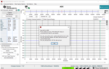
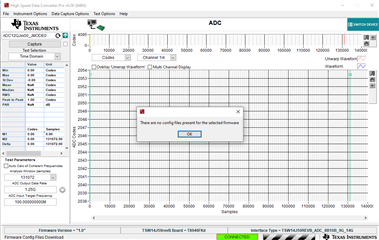
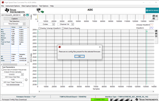
After configuring the ADC Board using the corresponding EVM GUI, and launching the HSDC Pro software, we can load the FPGA firmware but we don't have supported JMODEs (JMODE0) corresponding to the recommended ones in the documentation. Trying to use one of the others available options, after changing the ADC configuration, resulted on the following error message.

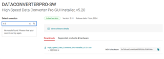
The documentation mentions INI files that need to be downloaded and added to the HSDC Pro instal folder, but the files that we could find on the EVM page correspond to the TSW14J57EVM, which uses a different FPGA.

Are those files available anywhere? Does anyone know another workaround?

Thanks in advance,

Fabio Kelm Pereira

  • Hi Fabio,

    Lets start with the ADC12QJ1600, you just plan to use JMODE0? At what sampling rate?

    Once I know these details, I will set it up in the lab and verify.

    Thanks,

    Rob

  • Hi Rob, thanks for the answer.

    We are running the ADC at 1600Msps, as said before, following the user guide documentation. That's the reason for using JMODE 0.

    Looking at the software, JMODE0 and other modes with 8b/10b configuration do not appear. We understand this is happening since there is no FPGA firmware supporting 8b/10b configuration on ADCs in the installation folder. We tried 3 different JMODEs that are listed in the HSDC software, 5, 6, and 14, and got similar error messages. In mode 5, we had to reduce the sample rate in the GUI to 800Msps, the error changed to the one bellow.

    Our application needs at least 1Gsps, but we are evaluating if a higher sample rate is beneficial. We are still considering which JMODE we will be using, but it will probably be either 5, 6, or 14.

  • Hi Fabio,

    Thank you for the details. I will set this up next week on the lab bench and provide you with an update.

    Regards,

    Rob

  • Hi Fabio,

    I set this up in the lab for JMODE0 and had no issues running this.

    Can you please let me know how you are configuring the ADC GUI?

    Ext clock or using the LMK clock SMA? Or something else.

    "I used Ext CLK from LMK to ADC", 1600MSPS, JMODE0, program clocks and ADC.

    Also, please let me know what version of HSDCPro you are using, I used v6.00 (64bit).

    Please advise.

    Regards,

    Rob

  • Hi Rob, thanks for the answer.

    As previously stated, we were trying to follow the procedure provided in the User`s Guide for the EVM (slau808).

    When configuring the ADC12QJ16000 using the ADC GUI we tried to use both the option Ext CLK from LMK to ADC, as it is first suggested in the user guide, as well as the onboard 50M Ref to ADC PLL. We've made tests using Fs = 1600Msps and Fs=800Msps and with JMODE0, 5, 6, and 14. After programming the ADC on each different configuration, we always made sure to disable the JESD Block and calibration controls and enable them back again after programming to ensure the programmed changes were in effect.. We've also always checked the indicator "leds" in the GUI to check status, and checked SERDES PLL LOCKED, SYNC STATUS and LINK UP were always on, which, in our understanding, indicate that the JESD block is operational and working correctly on the ADC side.

    Regarding the HSDC Pro, we are using version 5.2 since that is the one available from the software webpage: https://www.ti.com/tool/DATACONVERTERPRO-SW. If you could test it in this version of the software and see if this is the issue, that would be great.

    If you could also provide us with version 6.0 we can make new tests and see if it works properly.

  • Hi Fabio,

    At the HSDCPro site on TI.com, you can download both v5.2 and v6.0

    Its mis-labeled, I have requested this to be fixed, so please try downloading both links there at the site.

    Let just with JMODE0, open the GUI and click on update temperature, this tells me the GUI and ADC are talking.

    Then use the Ext CLK from LMK to ADC, type in 1600MSPS in the GUI and click program.

    This is assuming 1600MHz is applied at J31 at 10dBm and ~100MHz is applied on one of the AINP SMAs for one of the channels around 0dBm.

    After you program the ADC using the GUI on the first tab, move to the Control tab. Click on the check CAL Status. There are three indicators, which should turn green after you click this. Then click on the Cal triggered/running checkbox and click again on it.

    No need to do any of the other things. Move to HSDCPro and select this JMODE0 ini file for the QJ1600. Once the FW is programmed, then enter the proper sampling rate in HSDCPro and click on capture.

    You should get a noise floor with a ~100MHz tone.

    If something else is still not wrong, make sure the 12V supply to the TSW EVM is 5A current limit. This is needed for the FPGA to program correctly.

    The ADC EVM should have a current limit of 3A.

    Regards,

    Rob 

  • Hi Rob.

    There is clearly a big misunderstanding here. Let me address each point of your

    At the HSDCPro site on TI.com, you can download both v5.2 and v6.0

    Its mis-labeled, I have requested this to be fixed, so please try downloading both links there at the site.

    Either there is some region lock bloking me from acessing, or we are not acessing the same link. Here ia screen capture of the webpage: https://www.ti.com/tool/download/DATACONVERTERPRO-SW

    As you can see, there is no 6.0 version available. Have you tried running an older software version to see if this is an issue, as I asked before?

    Regarding the HSDC Pro, we are using version 5.2 since that is the one available from the software webpage: https://www.ti.com/tool/DATACONVERTERPRO-SW. If you could test it in this version of the software and see if this is the issue, that would be great.

    Looking at the list of supported hardware for the DATACONVERTERPRO-SW, the board TSW14J59EVM is not listed. Are you using it or an older board? Can you please detail your setup a little more?

    Let just with JMODE0, open the GUI and click on update temperature, this tells me the GUI and ADC are talking.

    Then use the Ext CLK from LMK to ADC, type in 1600MSPS in the GUI and click program.

    We did that, all lights are green, and it seems the programming of the ADC board is fine. The GUI works perfectly, we do not see any signal when using the Data Capture software for the interface with the FPGA board.

    No need to do any of the other things. Move to HSDCPro and select this JMODE0 ini file for the QJ1600. Once the FW is programmed, then enter the proper sampling rate in HSDCPro and click on capture.

    When talking about .ini files, I imagine you talk about these ones.

    As you can see, the files downloaded directly from the ADC12QJ1600EVM website are ones from 2019/2020, and are clearly labeled to the TSW14J57RevE, which is not our card and uses a different FPGA altogether.
    All our attempts come from selecting the device in the dropdown menu on the High Speed Data Converter PRO capture window, and the errors are already listed in my previous posts.

    We've noticed that for the TSW14H59 RevB board that we have the software pulls the JESD configuration parameters from a excel file named 14J59revB_Mode_Details.csv located in the folders "14J59revB Details\Device Files". On this file the only available configurations that exist for the ADC12QJ1600 are the ones shown in the picture below.

    We have also tried to create a new entry for this table that corresponds to the configuration parameters needed for JMODE0 that can be found on the ADC12QJ1600 datasheet, but when doing this, the software throws a misconfiguration parameters when trying to read the new input that we've created.

    If something else is still not wrong, make sure the 12V supply to the TSW EVM is 5A current limit. This is needed for the FPGA to program correctly.

    The ADC EVM should have a current limit of 3A.

    We are currently using 2 bench PSUs for each card. The one for the ADC can supply up to 3A, while the FPGA's one can supply up to 10A. This should not be an issue.

    If there are more doubts on your end, maybe we can arrange a call between us.

  • I double check all links in the page and they are possible fixed in a different way. Now both links are tagged as 5.20 and both leads to download page of 5.31 file. There is no link to v6 on page. 
    If I look for other versions, only v5.3 and v1.0 are available to download. I did not succeed in any search for version 6 too.

    Do you matter to point to v6.0 version ? As I am afraid fixing it on page can take to long is it possible to share a personal/private repo link with this version with us, please?

    Thanks a lot for all support. 

    Best Regards,

    Renato 

  • Fabio, Renato, I do apologize, I do not see HSDCPro V6.0 on the web either. Please download it here. See below. You have 24hours before the link expires.

    I am using a J59, REVB for the setup.

    Thanks for your patience, we are going thru alot of web updates for many of our converter products and there must have been some mis-communication.

    If v6.0 does not work, we can setup a call.

    Regards,

    Rob

    https://tidrive.ext.ti.com/u/6xLPjtuSz7P5Es-B/bb067bc5-fb6e-47b2-8418-37ab92a37b9f?l

    access code: p1;vzr7J

  • Hello Rob

    Thanks for the link. We downloaded and installed the version 6.0 in our machine.

    This has allowed us some progress: using a external signal for the Ref. Clock, we were able to make the ADC
     work in JMODE0, the capture is as expected. We are using a RF generator for the 1.6GHz signal for that, and another wave generator for the input signal.

    However, when using the internal PLL, we're still facing a similar issue as before. Here is the message that appears.

    We've confirm the PLL does get locked, not only via software. We also made sure that the input reference clock (50 MHz) is correct by measuring it on resistor R231. Here is a screenshot showing the PLL locked screen.


    We think this may be a problem with some configuration on the capture card side, since the ADC seems to be fine. Could you provide any additional insight for us?

  • Hi Fabio,

    Please confirm the JMODE and sampling rate you are trying when using the internal PLL and I will work thru this tomorrow on the bench to see what the issue is.

    JMODE7, 1.6GSPS?

    Regards,

    Rob

  • Hello Rob,

    It seems there was a miscommunication between me and the test engineer. Let me explain what is happening.

    For any 8b/10b modes, like JMODE0, the capture card gives an error like the ones below.

    While using a 64b/66b JMODE, this does not happen. For our application, we can use these modes work, so going forward I think we should look at them. We were only using JMODE0 as it is the one especified in the User guide, just that.

    However, when using the internal PLL, we're still facing a similar issue as before. Here is the message that appears.


    For your tests, you can use either the JMODE6 or JMODE7. Both of them work for our application, and both give off the same error if using the internal PLL, as per the image in the last post.

    Regards,
    Fabio

  • Hi Fabio,

    Thank you for the details. I will work on this in the afternoon today and provide some feedback.

    You may need to modify the EVM in order to do what you need. Let me research that as well and I will get back with you.

    Regards,

    Rob

  • Hi Fabio,

    For JM6 and JM7, we can support JM7 or use JM0 or JM8 in substitution to JM6. The performance is the same. For JM6 we would need to develop FW for the FPGA as the data is packaged differently.

    See attached JM7 ini file, this goes in the HSDCPro root directory where all the other ini files are located.

    C:\Program Files (x86)\Texas Instruments\High Speed Data Converter Pro\14J58 Details\ADC files

    We also found an issue with the ADC GUI.

    Start on the EVM tab of the GUI as you normally do, after you program the device, go to the ADC PLL tab, click on the "check PLL status" the PLL Locked box, should turn green. But it is red.

    In order to get the internal PLL to lock, do the following, go to the Low Level View and click on reg address 0x53. In the write data box, it says x83. Which is correct, but for some reason this is not being programmed. So delete the x83 and retype x83 in the write data box and hit enter. Then click read data box. It should show x83.

    Now go back and check the PLL status and the PLL Locked box should turn green. In the ADC PLL tab

    Next, go to the TRIG OUT tab and find the RX_DIV, cycle the DIV setting so it sets properly. You can also verify this in this in the low level tab once you cycle this.

    Now go to HSDCPro and you should get a clean capture.

    Please try this and see if you can get it working on your end.

    Thank you for your patience.

    Regards,

    Rob

    https://e2e.ti.com/cfs-file/__key/communityserver-discussions-components-files/73/ADC12QJxx00_5F00_JMODE7_5F00_1G_5F00_1p6G_5F00_50MHz.ini

  • Sorry, reg address should be 0x58

  • Hi Fabio,

    I apologize for all the posts. I got ahead of myself.

    In order to get what I was saying to work above, you need a J58 data capture board. Not a J59.

    This is true for all internal PLL configurations on the QJ family.

    So, if interested, I can exchange your current J59 for a J58.

    Please advise.

    Regards,

    Rob

  • Closing this post, reaching out to the customer offline.