This thread has been locked.

If you have a related question, please click the "Ask a related question" button in the top right corner. The newly created question will be automatically linked to this question.

ADS7953: Reliably enter Auto-1 mode

Part Number: ADS7953

Tool/software:

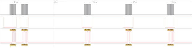
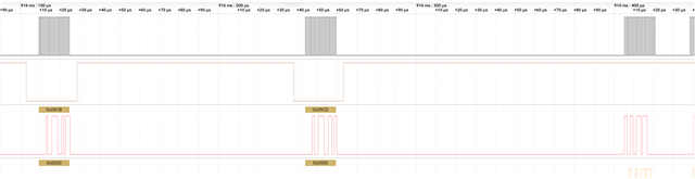
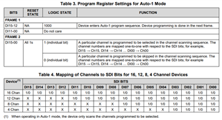
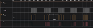
For a while, I had been able to successfully enter Auto 1 mode by passing the command 0x2400 followed by 0x0000, 16 times to get each of the channels.  Something happened, now each result is uniquely that of channel 0, 16 times.  How do I reset and reliably enter Auto 1 mode?

  • Hi Danny,

    Can you share a logic capture of your SPI communications? When you say you were able to get it before, but not now, is it the exact same sequence that you're providing, or did anything change in hardware or software?

    Regards,
    Joel


  • Through to the 16th packet:

    Then switch to programming an LT DAC.

    Yes, exactly the same sequence.  I'm fairly confused because on page 36:


    With page 37 indicating:


    I'm using:


          xfer(0x2000);   //  Auto-1, Logic State

    Presuming Table 2 is correct.  No progress with cmd == 0x8000

    I thought I was on easy street when 0x2000 worked but before I power-cycled the DEV board
  • Hi Danny,

    It looks like you're using a Saleae, so could I ask you to export the logic capture as a file, zip it, and attach it here? I can take a closer look in the Logic program, and verify if any timing might be off. At a glance, this seems to be correct. 

    Regards,
    Joel

  • Hi Danny,

    So it looks like you are not entering the auto-1 programming mode (0x8xxx). The reset state is supposed to have all channels enabled, so maybe at some point you sent the 0x8000 command, but no data in the second frame, disabling all channels.

    Have you reset or powered down the device between your tests to see if the expected operation begins again? You can do a reset via software while writing to the GPIO program register (DI[15:12] = 0b0100) and setting DI09 high.

    Also to clarify, are these transactions while ~CS is high controlling the other DAC device you mentioned? 

    Regards,
    Joel

  • I know Channel 0 always worked fine, so I didn't disable ALL the channels.

    Following your suggestions, I sent 0X8000 followed by 0XFFFF and it seems to work, thanks!

    From the manual, how do I know Table 3: Logic State is what I'm supposed to use versus Table 2: Reset State or Logic State?

    8015.ADC.zip

  • I did notice that for channel 1 on my dev board, 10% of the readings are near zero, the rest accurate; and the other 4 channels I'm connected to are accurate all the time.  Is it possible channel 1 is partially damaged?

    My use case is a controller with 4 of these ADCs, connecting to 37 channels out of 64 total, so if I reconfigure to skip a channel it's okay.

  • To answer your first question, table 3 applies only when programming the channels you will be using in auto-1 mode. When you actually want to enter auto-1 mode and cycle through the channels, that's when table 2 applies. Table 2 also contains some configuration parameters, such as the input range, channel reset, powerdown mode, output data format selection, and GPIO control (when configured as outputs).

    It may be possible that it is damaged. If you get close to zero readings occasionally, I suggest tying the input to the analog supply, taking a bunch of samples, and any that aren't 0x1FFF might be signs of a fault. I'm not sure I've seen that failure signature though. If it is damaged, it will usually be consistent bad data. 

    Regards,
    Joel

  • Cool, thanks.

    What is the difference between Reset and Logic State?

  • Reset state would be the default values on power up or on a reset. Logic state is the bits that correspond to the instruction, i.e. the actual instruction word. So if you want to operate in auto-1 mode per table 2, your input word could look like 0x2840. Here, auto-1 mode is selected, writes to DI[10:0] are enabled, and 2*Vref input range is selected. 

    Regards,
    Joel