This thread has been locked.

If you have a related question, please click the "Ask a related question" button in the top right corner. The newly created question will be automatically linked to this question.

AMC0106M05: Output failed

Part Number: AMC0106M05

Tool/software:

Dears,

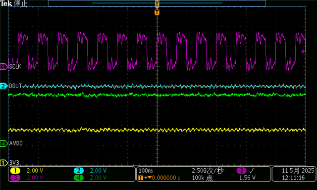
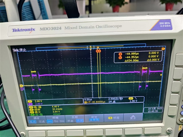
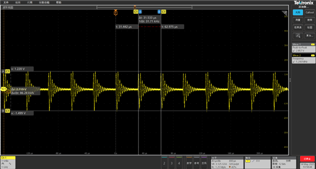
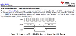
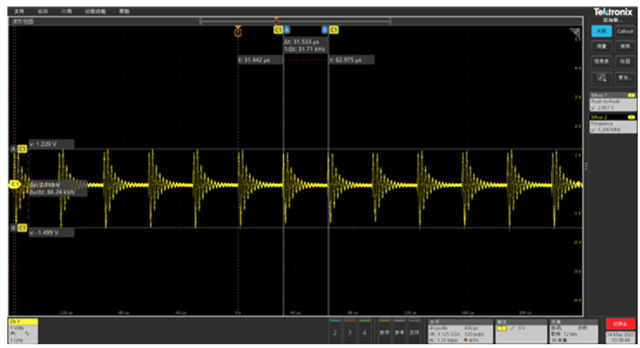
  In some scenarios, there is no output phenomenon, but AVDD DVDD CLKIN works normally; The only way to recover is to restart AVDD, and then the output will return to normal.

  • Hi, 

    Thank you for bringing this issue to our attention. Is there any additional background that can be provided? 

  • Hi

    Customer's servo drive project uses AMC0106M05 for current acquisition and has already been mass-produced. However, occasional overcurrent errors are reported in product usage feedback from end customers. After investigation, it was found that it was caused by no output from AMC0106M05, and the data collected by the DSP ADC was overcurrent. Failure is not a repeated occurrence, but an accidental phenomenon that cannot be replicated every time. It requires testing for a long time to obtain the failure phenomenon.

  • Hi, 

    So how is it verified that AVDD, DVDD, and clock are working normally during this scenario? 

    Are oscilloscope pictures showing these signals and DOUT available during the fault? 

  • Hi,

       The AVDD DVDD DOUT waveform as below, the unstable waveform is due to the length of the test lead

  • normal waveform

  • Hi, 

    Thank you for the reply. Can you please comment on who the customer is?

    Is the team actively testing to understand the status of the application when the fault first occurs? 

    I will check with my team on the situations that would cause this issue. 

  • Hi 

      Customer confirmed the application as below,

    Product Description: product is a motor drive module, which includes a driver encoder and a motor, integrated together. One motor drive module includes 15 H-bridge drivers and 15 motors, each H-bridge using one AMC0106, for a total of 15pcs AMC0106.
    Experimental process: A whole line, 2 meters long, with 8 modules. The time for the fault to occur is uncertain, possibly tens of minutes or even tens of hours. The fault always occurs when the first coil of the sixth module reports a fault. If the sixth module is swapped with any other module that has not reported a fault, it will still report a fault on the first coil of the sixth module. The test shows that the problem is caused by the current sampling of the same H-bridge coil at the same position (the first coil among the 15 coils).
    Based on the above tests, our preliminary judgment is that it should be related to the actual operating conditions, which caused the abnormal BUG in 0106.

    IC operating condition description: H-bridge topology currently intermittently opens the left lower bridge arm to continuously charge the AVDD of AMC0106. Our driving waveform is shown in the figure, with the red 3 channels being the GS waveform of the left lower bridge arm driving the H-bridge, and the yellow 1 channel being the GS waveform of the right upper bridge arm driving the H-bridge, with a frequency of 32K.

  • Hi, 

    Ok, so this confirms is it related to module #6, not the particular AMC0106 devices. What is different about module 6 with respect to the rest? 

    Is this module farther from other in terms of the DCBUS+ supplies?

    Are there any loads near module #6 that could create an EMI issue? 

  • Module 6 is not farthest from DCBUS, and modules 7 and 9, which are farthest from the power supply, have no problem.
    Yesterday during an experiment, module 6 was replaced with a new GaN module solution, and the fault was changed from module 6 to module 3.
    AVDD load current waveform of 1A, disabled state.


    Enable state


    Motor closed-loop control to 1A current AVDD waveform

    The current solution for the customer is to reset AVDD using a program after a malfunction occurs. But the customer wants to find the cause and solve the problem from the root.

  • Hi,

    For the unit's that have failed, can you please check the output to see if there is an opposite polarity pulse every 128 clock cycles? 

    It would be helpful to check exact AVDD signal by short probe ground or COAX connection across C33 to confirm the magnitude of the high frequency ringing. 

    Assuming that this ringing on AVDD (either coupled or conducted) from the gate driver is causing this issue to occur, a snubber or capacitance multiplier on the AVDD circuitry to increase robustness of the AVDD line may be helpful. 

    This would help from the AMC side, but likely best course of action would be to find the cause in the bridge circuitry for this ringing and try to improve settling. 

  • HI

    1. Customer can confirm that it is not caused by input overvoltage and there is no opposite polarity pulse every 128 clock cycles.

    2. short probe groud, The customer conducted a test using a spring needle, as shown in the following figure. AVDD


    The waveform after testing with an isolation probe. The peak value and amplitude may not be correct because the high-voltage isolation probe has a relatively large amplification factor and a small bandwidth.

    Add a 2.2 Ω resistor as a snubber and a capacitor of 4.7uF, but the problem persists.

  • Hi, 

    Thank you for confirming. This looks like the device is recognizing a missing high side supply. 

    From the first waveform, the lowest voltage marked by the cursor would suggest AVDD = 2.719V - 1.499V = 1.22V. 

    This is well below the minimum AVDD_UV detection threshold. The rapid change in AVDD voltage in combination with the repetitive nature of the undervoltage is likely causing this behavior in the device. 

    Two things to try: Reduce the ringing as mentioned in my previous post and/or increase the settled voltage to be greater than 2.719V. Keep in mind that if this is done, then the over-shoot should not exceed the absolute maximum ratings of 6.5V. Keep in mind that the probe bandwidth may limit the true over/undershoot value and could be beyond what is captured by the scope (as mentioned in the HV probe picture). 

  • Is the waveform tested by the customer using a passive probe effective?

  • Hi, 

    I'm not sure what you mean? 

    It looks effective enough to understand the device specifications are being violated.