This thread has been locked.

If you have a related question, please click the "Ask a related question" button in the top right corner. The newly created question will be automatically linked to this question.

ADS1263: Multiple input calibration and configuration settings

Part Number: ADS1263

Tool/software:

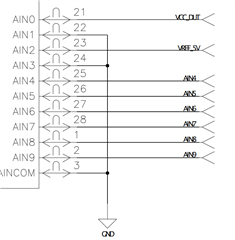
I am working with the ADS1263EVM-PDK Evaluation Module to assess compatibility for the ADC in a test system design. The ADC is intended to be used as an "equivalent" high-resolution DMM replacement. This system includes both differential and single ended inputs with a 0-5V range. My reference voltage comes from a 5V ultra low noise precision regulator connected on pins AIN2 and AIN3.

As far as calibration goes, its my understanding self offset calibration can be done by floating the inputs and sending the appropriate command with the PGA enabled. As far as Full-Scale System Calibration goes, what is the input voltage I should use as reference considering I will be using the ADC for both differential and single ended voltage levels? Should the PGA be enabled or disabled for this? Are there differing calibration procedures for single ended vs differential measurements or is a single calibration valid for both measurement types?

Additionally, ADC will likely be configured for varying gain settings depending on the expected input signal span. Does a calibration need to be done for each gain setting?

The SPS and filtering are fixed.

AIN4-AIN5 Differential signal

AIN6-AIN7 Differential signal

AIN8-AINCOM Single Ended

AIN9-AINCOM Single Ended


  • Hi Ammar,

    When doing a Full-Scale System Calibration, a positive full-scale dc signal should be applied to the ADC theoretically, however using a little bit smaller signal (95% full-scale input signal as an example) is a good practice to avoid clipping the input signal. See the recommendation from my colleague in this E2E post: ads1263: Self Calibration vs. User Calibration

    ADS1263 always measures or converts the differential signal between two input pins including a single-ended input configuration, so you can just do the calibration with one of the configuration (e.g. differential input) at the Gain configuration you need. Generally, performing separate gain calibrations is recommended for each gain setting since the gain error may be slightly different with each gain configuration. If there is a large gain error external to the ADC, then performing a single gain error calibration for all the gains may be beneficial.

    I noticed you are trying to measure a single-ended input signal on AIN8 and AIN9 by shorting AINCOM to the GND. ADS1263 supports either a unipolar power supply (AVDD = 5V, AVSS = GND) or bipolar power supply (AVDD = +2.5V, AVSS = -2.5V), but the EVM only supports the unipolar power supply. When using a unipolar supply, you can only measure ground-referenced input signals with the PGA bypassed. If you want to measure a ground-referenced input signal with a Gain on internal PGA, you have to use a bipolar power supply.

    There is one option to measure a single-ended signal when using the unipolar power supply, you can measure it with a level-shift voltage (Pseudo-Differential Input Mode). Please refer to section 10.1.2 ("single-ended measurements")  in the datasheet for more information about level-shifting the negative input pin to an offset voltage, which can allow a wider use of the ADC's full scale range compared to grounding the AINN pin.

    BR,

    Dale