This thread has been locked.

If you have a related question, please click the "Ask a related question" button in the top right corner. The newly created question will be automatically linked to this question.

AMC131M03: CRC issue

Part Number: AMC131M03
Other Parts Discussed in Thread: ADS131M04

Tool/software:

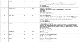
Hi im using  AMC131M03 IC, in that im facing an issue i have configured data for 16bits , dcdc enabled and OSR of 128 , all are working fine. but sometimes my crc is not matching lets say once in an 300 or 400 reads, during that time im getting an value in status register is 0x0203 , which means last channel data is not ready and word length is showing 32 bits and reset bit is  0 showing no reset occured.

during when my crc is correct , my status register is showing 0x0407 , always  which means all channels data are ready, word length is 16bit and reset bit is 1 indicating reset is occured.

but this is happening once in every some 200 to 400 between reads and and after that again some 200 to 400 times crc is matching , what could be the reason. what that reset bit indicates in status register and what is the use. during continuous reading what value that reset bit should be. 

can someone  suggest how to rectify this. during all these check im not giving any input to channels of ic , im just trying to read and write and verify the crc

regards,

srinath

  • Hi Srinath,

    my status register is showing 0x0407

    This Status word indicates that a reset has occurred.  Is that expected?

    The Reset bit goes high when the device has gone through one of the three:

    1. Reset pulse is given to the RESET/Sync pin
    2. Reset command is written to the device through SPI.
    3. Power has been cycled to the device.

    Are you resetting the device at all during your testing?  Is it possible there is a voltage drop causing a reset?

    Thanks.

  • Hi saleh thanks for the response, if reset is occured means device has to go default values, but im again started getting the value of 16bits and some crc matching. during the continuous reading the reset bit should be 0 or 1. and in between im not giving any reset command or sync reset.

    what could be the problem

    thanks,

    srinath

  • Hi Srinath,

    Do you have SPI captures of the frame that fails the CRC and the frame right before it?

    Thanks.

  • hi saleh sorry i have written the data in note only, please check and tell what could be the reason for crc failing. since hold_out  pin is generating 2.94v and input voltage is 3.3v. before often only crc will fail now frequently one after another time crc is failing. and im working with both ADS131M04 and AMC131M03 together using single spi bus and im not considering the drdy, due to multiple interrupts. and im checking individually only AMC131M03 IC, another ic chip select will be high. what could be the reason, initial parameters configurations are setting and verified now the crc failing frame is different than before. please suggest some solution.

    regards,

    srinath

  • Hi Srinath,

    What is happening with the SYNC/Reset pin on the device during this testing?  Could you try running your test with that pin set high permanently?

    The data in your picture above shows a Reset and Sec_Fail,  is the reset expected?

    Thanks. 

  • Hi saleh,

    sync pin is permanently high only. i think these issues are coming due to timing issue between two ic of AMC131M03 and ADS131M04. now im not getting this issues. now i want to do gain and offset calibration. due to resistors tolerance, how can i  add it in devices, since im using 16bit mode , so initally i have to do calibration and then i have to change length to 16 bit mode.  at zero voltage at input of amc131m03 i reading an value of 250 around in channel 1 and 2 , and channel 0 is fine. that 250 initally adc value correspond to 3.5volts , so how to resolve this offset and gain problems. in channel 1 and 2 im reading line to line voltage of 410v and peak of 580v so same will come in negative cycle aslo.so the maximum input to device after resistor divider is 1.193. so at zero volt im getting an some offset  also and resistor tolerance also there of around 80k ohms. how to add calibrations for this 

    regards,

    srinath

  • Hi Srinath,

    For calibration you should do the following:

    • Record the device measurements for 2 input points (0 input and maybe around 20% of full scale input). from those 2 points you can determine the offset and gain calibration factors.
    • You can then input those values into the devices calibration registers (Section 8.3.13 of the datasheet goes over this) or use the values in your SW to calibrate after reading the device data.

    Thanks.