This thread has been locked.

If you have a related question, please click the "Ask a related question" button in the top right corner. The newly created question will be automatically linked to this question.

ADC12020: The offset error is too high

Part Number: ADC12020

Tool/software:

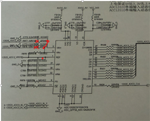
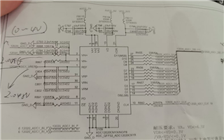
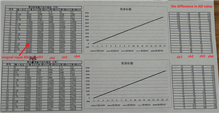
Dear Expert We use singel end input ,and use REF5020 as 2.048V ref voltage,now we test found that the offset error is too high.

And different IC could have different offset error.

Below is schmetic ,could u hlep to check how to prevent these offset error?

  • Hi Gabriel,

    If you disconnect the analog inputs and tie them together. Is the offset still too high? Remove R888/R889 for example. Then measure.

    If not, then the offset is coming from the circuit before the ADC.

    Using an external reference will not change or improve the offset, external references will only improve the gain error of the ADC.

    Regards,

    Rob

  • Dear Rob

    1.There are no peripheral circuits here. Directly provide a fixed signal source generator signal. All chip inputs are tied together, resulting in differences in chip acquisition results.

    2.And the magnitude of the linear slope exhibited varies.

    So the customer believes that the inherent large offset of ADS12020 in single ended input scenarios is not suitable.

  • Hi Gabriel,

    so the results above are with the signal generator disconnected? And the input shorted together?

    Please see my pic below. Like this? Please verify.

    Regards,

    Rob

  • Dear Rob

    Vin- conected the 2.048V and Vin+ conected 0-4V Vin.

    We do test again:

    (1) Disconnect the other ADCs and keep only one ADC with the same test result as before, without any changes.
    (2) At present, the test results can basically eliminate errors caused by circuit and surrounding interference.
    (3) The measurement error of different chips follows the chip, and the same chip is soldered to different channels to maintain the same test results.

  • Hi Gabriel,

    The customer is still not giving me enough information to help.

    I cannot tell from the previous post if there is a problem still.

    The schematic is not correct, VREF should not be connected to VIN- and also connected to a signal generator.

    It would be very helpful for the customer to send details, block diagrams on how they are testing this.

    Regards,

    Rob

  • Hi Gabriel,

    Closing this post and taking this offline. Please see my email.

    Regards,

    Rob