This thread has been locked.

If you have a related question, please click the "Ask a related question" button in the top right corner. The newly created question will be automatically linked to this question.

ADS1261: ADS1261 breakout board design

Part Number: ADS1261

Tool/software:

Hi,

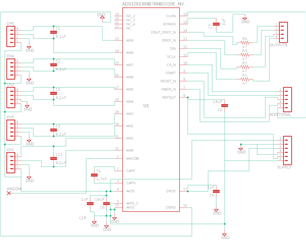
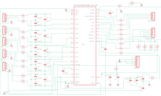
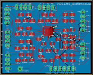
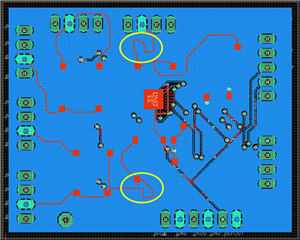
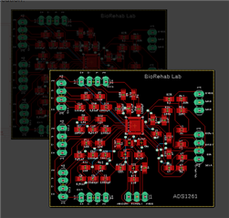
We are trying to develop a breakout board for ADS1261 which we will be using for our in-house built force platforms. We have designed two circuits for the same, please find the attachments. Design-1 is based on the layout mentioned in page no. 82 of ADS1261 datasheet (https://www.ti.com/lit/ds/symlink/ads1261.pdf?ts=1747206472285&ref_url=https%253A%252F%252Fwww.ti.com%252Fproduct%252FADS1261), and Design-2 is based on the circuit diagram provided in page no. 25-26 of ADS1261 EVM user guide manual (https://www.ti.com/lit/ug/sbau293a/sbau293a.pdf?ts=1747133881840&ref_url=https%253A%252F%252Fwww.ti.com%252Ftool%252FADS1261EVM). Kindly help us to understand which circuit is appropriate to go ahead with for designing the breakout board for ADS1261.

Thank you,

Charles

  • Hi Charles,

    I could not see any difference between two block diagrams you uploaded. Page no. 82 in ADS1261 datasheet shows a PCB layout, but page no. 25-26 in ADS1261 EVM user guide shows a schematic, so can you clarify what the difference between your two circuits is?

    BR,

    Dale

  • Sorry for the mistake. Here are the two design

  • Hi Charles,

    Thanks for your clarification. The figure 103 in no. 82 of ADS1261 datasheet focuses on a layout example, the circuit in the figure is a simplified circuit. The circuit in the ADS1261EVM user guide is a practical and recommended circuit. For example, not only a differential capacitor but also common-mode capacitors should be used, see the guideline [FAQ] Delta-sigma ADC anti-aliasing filter component selection

    BR,

    Dale

  • Hi,

    Thank you for your reply. I have a few more things to clarify. Here, I have attached the PCB layout of the ADS1261 breakout board that we have designed, could you please confirm that everything is alright or not? I have attached the corresponding GND connection layout as well, kindly confirm is this okay or not. Also, there is a long trace of wire for DOUT/DRDY pin, that's why we have used a 47 ohm series resistor, is it enough? Kindly check and help us to learn better.

    Thank you,

    Charles

  • Hi Charles,

    It's very hard to review a layout from the images. I can not see the signal and also the labels in your images. Here are few suggestions I have so far:

    1. Place the components especially the differential cap/coupling cap on the power supply/cap on the reference close to the device.

    2. Use a solid ground plane if possible.

    3. The value of the series resistor depends the source impedance, the impedance of your trace etc., you need to calculate them, otherwise use a 47ohm as a start point and optimize it later.

    4. Use a short trace if possible, for example, I'm not sure why your traces highlighted in yellow below looks so weird:


    BR,

    Dale

  • Hi Dale,

    Thank you for the suggestions. I have tried to incorporate the things you have mentioned. Attached images are the modified ADS1261 break out board schematic, PCB  layout and the corresponding GND connections (blue rectangle indicates the ground plane). Please let me know if our circuit seem okay or not, can we proceed for fabrication? 


    With regards

    Charles

  • Hi Charles Jebaraj,

    Can you make the images bigger? For example this is what I see when I click on the more detailed image. See how it does not get bigger? You can change the scale of an image by clicking on it before you post, then hitting "Edit". You can always check the post once you've hit "Reply" to make sure the images are a good size

    Are you just using a 2-layer board? And now there is no ground pour on the top layer?

    I'm also not clear about what I am seeing in the second image with the ground plane. Why are some of the top layer traces (red) showing on this layer?

    -Bryan