This thread has been locked.

If you have a related question, please click the "Ask a related question" button in the top right corner. The newly created question will be automatically linked to this question.

DAC39RF10-SEP: Required bias circuit at DAC output

Part Number: DAC39RF10-SEP

Tool/software:

Hello, 

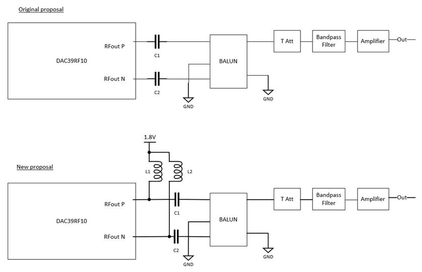
In some parts of the DAC datasheet there are mentions to the DAC output voltage, and output bias, but there is no explicit suggestion or requirement about an external bias network.

  1. Is it mandatory to include an external circuit to bias the DAC output when AC coupled?
  2. What type of network is recommended? Can it be a simple resistor divider? 
  3. Can the component be damaged if no external bias is provided?

Thank you.

  • Hi Sergio,

    1) yes, you need to include the external bias circuit on the output of the DAC for it to work correctly when AC coupled.

    2) The recommended network is in the datasheet and also on the eval brd. You can download the EVM design files and view the schematic portion and bill of materials for the exact part numbers used.

    3) Probably no damage, but the DAC will not work correctly.

    If there is something else you are trying to do with the DAC in particular, please let us know. As this is a different set of questions than normal.

    Please advise, as we are happy to help you.

    Regards,

    Rob

  • Hi Rob, thanks for your quick reply.

    I do not find the recommended network in the datasheet, could you point me to the page where it is discussed?

    Regarding the EVM, I see that, besides the Tee-bias, there is a T attenuator included in the output, before the balun. What is its goal? What would be the impact of not including the att.?

    We have quite strict board space constraints and it would be difficult to include the tee and the attenuator and the ac-coupling capacitors.

    Best regards, 

    Sergio

  • Hi Sergio,

    Correct, the analog output circuit recommendations are in the EVM design files. Sorry about that.

    The outputs will definitely, need a bias T that covers your frequency range.

    The output balun would need that too.

    As for the attenuation circuit between the biasT and balun. This is needed for this particular balun as the eval brd is setup for the widest BW possible by default.

    I am not sure of your frequency application band, so I can help make other suggestions if you provide me with some requirements.

    Regards,

    Rob

  • Hi Rob, 

    we plan to work with Fs = 8.52 GHz and the output frequency depends on the specific project, with a range between 2.8 GHz and 5.4 GHz.

    For clarity, I attach our original output proposal and the one that we'd like to implement now with a discrete bias tee. We still have to sort out the best passive values. Any suggestions?

    DAC output circuits

    Thank you.

    Best regards.

    Sergio.

  • Hi Sergio,

    Two things I would suggest.

    1) The biasT used needs to be rated for the output frequency BW you plan to use for the DAC.

    2) I would allow some matching circuit allowances between the caps and the balun as noted below.

    You can put the three resistor T attenuator pad there, make the component 0ohms for the series elements and DNI for the shunt elements.

    I am not sure which balun you plan to use, but just a general statement if you don't put some sort of matching elements between any DAC/ADC and connect the balun straight in, the BW typically suffers.

    Regards,

    Rob