


Other Parts Discussed in Thread: ADS8686S
Tool/software:
Dear TI Support Team,
I am currently working on integrating the ADS8686S ADC with a FTDI FT232H USB-to-SPI bridge and encountering issues while trying to read the Device ID (Register 0x10) via SPI in software mode. Despite verifying signal activity through an oscilloscope, I am receiving incorrect or inconsistent values (e.g., 0x0002, 0xFFFF, 0x0000) instead of the expected Device ID.
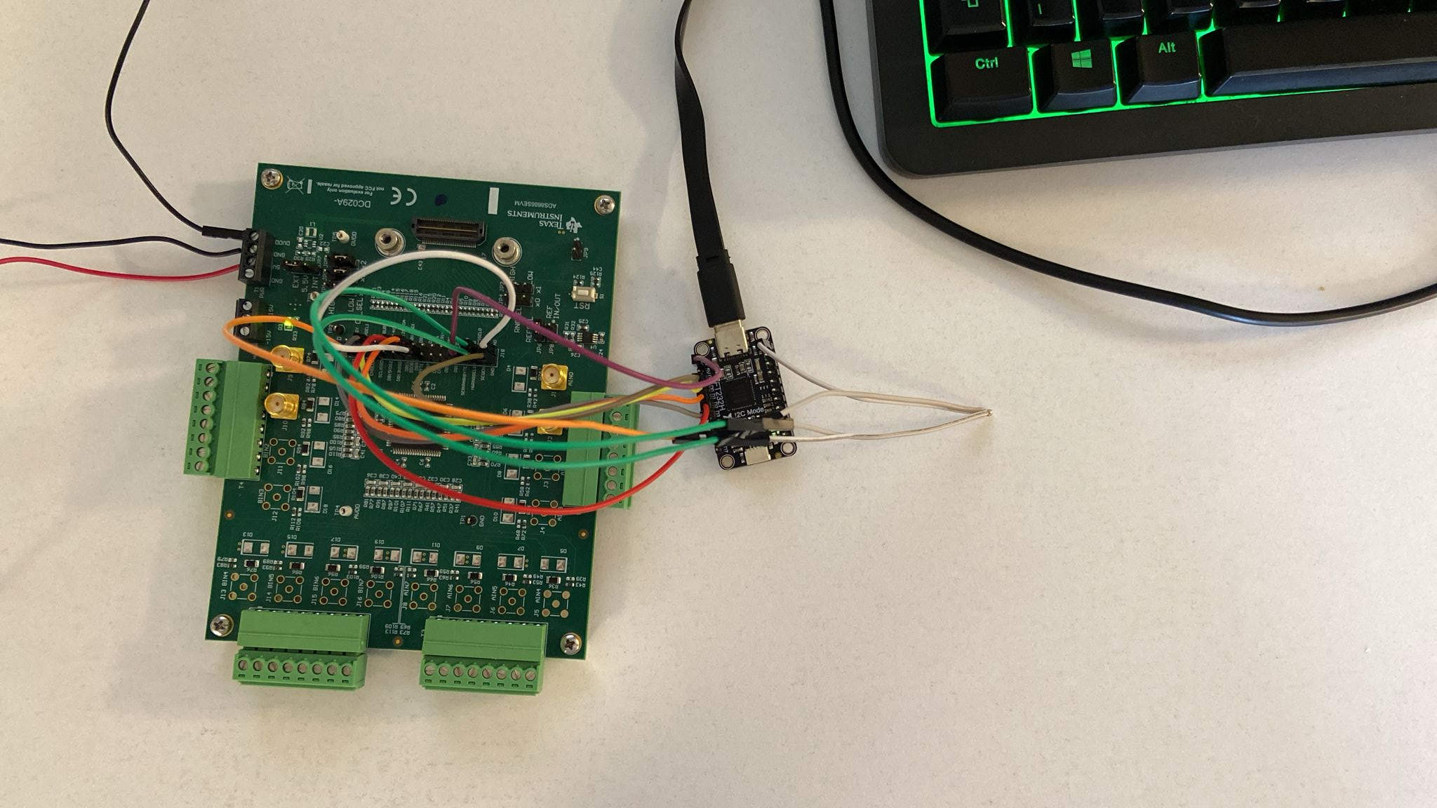
Hardware Setup
ADS8686S Supply:
5.5V → T1 PWR 5.5
3.3V → T1 PWR DVDD
FT232H I/O Voltage: 3.3V
Shared GND between ADS8686S, FT232H, and power supply
Pin Connections
| ADS8686S Pin | FT232H Pin |
|---|---|
| SER/BYTE/PAR (J18) | 3.3V |
| DB9/BYTESEL (J18) | GND |
| HWRNGSEL0 (J18) | GND |
| HWRNGSEL1 (J18) | GND |
| SCLK/RD (J18) | D0 (SCLK) |
| DB10/SDI (J18) | D1 (MOSI) |
| DB12/SDOA (J18) | D2 (MISO) |
| CS (J18) | D3 (CS) |
Note: R23 resistor on the ADS8686S board has been removed to allow SPI access.
Monitoring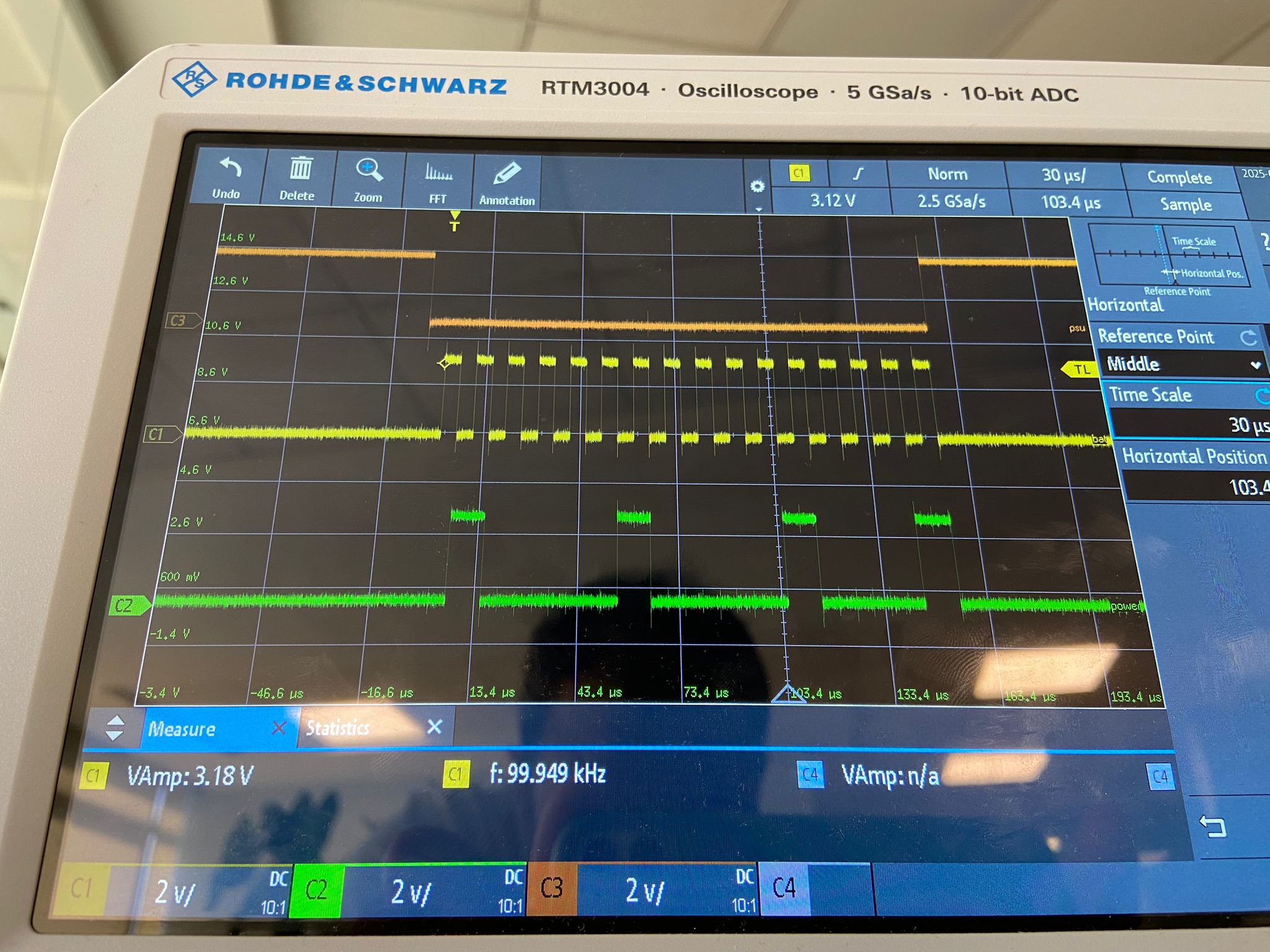
Software For Test
from pyftdi.spi import SpiController
import time
 Reading DEVICE_ID (Register 0x10)...")
 Device ID: 0x{value:04X} ({value})")
 No response received.")
SPI mode tested: 0 and 2
-
Mode 2 (
CPOL=1,CPHA=0) returns0x0002. -
Mode 0 returns
0x0000.
-
Oscilloscope Output: Confirmed proper SCLK and CS timing; data is transmitted as expected from FT232H.
Questions / Support Needed
-
Could the inconsistent Device ID values indicate a misconfiguration or hardware timing issue?
-
Is SPI mode 0 confirmed to be the correct configuration for the ADS8686S?
-
Is any additional configuration or initialization required on ADS8686S after reset to enable SPI register access?
-
Is there a way to verify that ADS8686S has entered software mode correctly (besides HWRNGSEL[1:0] = 00)?
-
Are there any known compatibility notes when using FT232H with ADS8686S?
