This thread has been locked.

If you have a related question, please click the "Ask a related question" button in the top right corner. The newly created question will be automatically linked to this question.

DAC8775EVM: Erratic SPI Communication

Part Number: DAC8775EVM
Other Parts Discussed in Thread: DAC8775,

Tool/software:

Texas Instrument Team,

I have been using the evaluation board for a little over a week and just recently began experiencing issues.

Earlier today, I attempted to configure an additional device to share the same SPI bus as the evaluation board. The new device samples data on the rising edge of the clock, while the evaluation board’s DAC samples on the falling edge. To accommodate this, I modified my firmware to support switching between different SPI modes on the fly, since the DAQ only supports data sampling on the trailing edge of the clock.

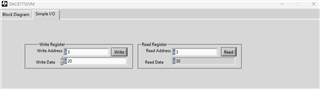
After successfully getting my sensor to communicate with the microcontroller, I noticed that the DAC was no longer responding correctly. To rule out a firmware issue, I switched to the development software and the SM-USB-DIG provided with the evaluation board, but the erratic behavior persisted.

The only hardware change I made was switching the jumper configuration: I removed JP9 and added JP13. I also connected the 3.3V output from my microcontroller to the bottom pin of J4, which is tied to JP13.

Even after reverting everything to the original configuration, the DAC still behaves unpredictably. It does respond, but the output does not make sense.

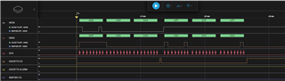
I’ve attached two screenshots showing communication before and after the issue occurred. The screenshots capture the start of a reset command for reference.

Any help diagnosing or resolving the issue would be greatly appreciated.

Thanks,

Jason Harrington

  • Jason,


    It's not clear what is wrong in the setup and I also wasn't sure about what issues you were having. Were you having problems with the read back? That seems to be what you are showing in the two diagrams (where the results are different for the same inputs).

    Regardless, let's start by simplifying the problem a little. First, I would just start with the control of the DAC8775 and disconnect anything else connected to the SPI. Second, for the read back of the register, I think the first frame of read is ok, with 0x820000. However for the second frame, I would write 0x000000 (instead of 0xFFFFFF). I think the NOP with zeros is necessary, and there might be problems interpreting the second frame.

    Start by checking this particular readback method and let me know if that works. After that, we can check adding in another device to the SPI bus.


    Joseph Wu

  • Thanks for your reply.

    The two screenshots represent the same configuration but with different results. The first result ("GOOD") was obtained when I initially tested the dev board using the provided SM-USB-DIG and DAC8775EVM software. The second result ("BAD") shows the same configuration—still using the SM-USB-DIG and DAC8775EVM software—but with an unusual response.

    If there is something wrong with the second MOSI frame, I don’t have control over it, as it reflects what the SM-USB-DIG does based on the instructions from the DAC8775EVM software. I had assumed that the dev software performs all operations correctly and could be used as a reference. Is that assumption valid?

    The main issue I’m trying to highlight is this: after sending the read command for register 0x82 (i.e., 0x02 | 0x80), I expected the DAC to respond with the same address as the first byte, followed by two data bytes. This behavior is seen in the “GOOD” screenshot. However, in the “BAD” screenshot, the response begins with 0x84 instead.

    Additionally, when I previously performed a "READ ALL" command using the DAC8775EVM software, all registers would populate with their default values—for example, all Buck-Boost options were disabled. Now, when I run the same operation, the register values are different; there are DAC offset and gain calibration values set, which I have never modified. This suggests to me that the responses from the DAC may not be correct.

  • Jason,

    Ok, I think that I understand the issue a little bit better. Generally, I would think that the GUI software would be representative of how you would want to communicate with the device. 

    In general, I've had pretty good luck using this EVM and I generally don't see many issues with it. That being said, I've looked at the signals on an oscilloscope before, I seem to remember the SM-USB-DIG gives some small SCLK pulses. Because of that, there might be some digital communication issues.

    One thing that I did notice is that your read request was for 0x82 and that it returned 0x84. If there's noise on the SCLK line, the device may have interpreted the noise as an extra SCLK pulse, advancing the clock by one. In that case, the device may have picked a pulse up even if the logic analyzer didn't. If you have a chance, I would try reading back something like 0x85 just to see if that gets changed to 0x8B. 

    If you see a bunch of registers that are set to something different that you expect, can you give me some different examples? It might help to look at other registers with the expected data and what you're actually getting. The DAC Data register at 0x05 is can be used because the register can be set to 16-bit value.

    Coincidentally, I'll need to use this EVM later. I'll take a look and see if I get any errant results in the EVM and see if there's any way I can add in some extra noise. 

    Joseph Wu

  • Jason,

    If this problem does come from a little extra noise in the SCLK line, you might be able to hang a 100pF capacitor off of SCLK to see if it helps.

    Joseph Wu

  • Jason,

    One thing that I just noticed is that the SDO line for the DAC8775 is always actively driven by default. I think it was done this way in case the device is used in daisy chain mode. This needs to be disabled before you have multiple devices on the SPI bus and tie all the SDO lines together.

    It's not described very clearly in the data sheet, but you should initialize the device to set the SDO line to be Hi-Z when /CS is high. This is done by setting the DSDO bit in register 0x03 to 1. After that, the SDO is driven when /CS is low, and Hi-Z when /CS is high (as expected in most SPI lines).

    Joseph Wu

  • Joseph,

    Thanks for your quick responses and the constructive suggestions.

    I’ve tried reading all of the parameters from the DAC, but I was unable to identify a consistent pattern in the responses when comparing the address sent to the address received. At times, the response appears to have the last four bits bit-shifted in one direction; other times, it seems to shift the opposite way. In some cases, I couldn’t determine any clear bit-wise relationship at all. Additionally, there were instances where I received the same response for different address bytes.

    Command Sent Command Received Note
    Hex Binary Hex Binary
    0x81 10000001 0x82 10000010 <<1
    0x82 10000010 0x84 10000100 <<1
    0x83 10000011 0x86 10000110 >>1
    0x84 10000100 0x88 10001000 >>1
    0x85 10000101 0x8C 10001100
    0x86 10000110 0x8C 10001100 >>1
    0x87 10000111 0x8E 10001110 >>1
    0x88 10001000 0x90 10010000 >>1
    0x89 10001001 0x94 10010100
    0x8A 10001010 0x98 10011000
    0x8B 10001011 0x9C 10011100
    0x8C 10001100 0x98 10011000 <<1
    0x8D 10001101 0x9C 10011100
    0x8E 10001110 0x9C 10011100 >>1
    0x90 10010000 0xA0 10100000 <<1
    0x91 10010001 0xA4 10100100

    In addition, I ran an experiment where I read the data from address 0x03, then wrote the same data back to that address, and subsequently read from the same address again. However, the response was different when I read the data back. I double-checked the communication using a logic analyzer and found complete agreement between the data sent and received by the SM-USB-DIG and what was shown in the DAC8775EVM GUI—all transmitted commands and received bytes matched. While the data exchange between the software and the SM-USB-DIG appears correct, the DAC’s response is not as expected. It either did not correctly receive the data I sent, or the response it sends back is corrupted or invalid.

    I tried to write to the DSDO bit, but I'm not confident that I am able to change the bit since the responses from the DAC are so erratic. I have also attached a screenshot of the GUI after performing a power cycle, RESET and READ ALL command. As I mentioned earlier, many of the values do no make sense as default values after a power cycle, such as the buck-boost enabled.

    I am happy to try the capacitor on the SCK line if you think it will help.

  • Jason,

    Out of curiosity, are you using the SM-USB-DIG, or are you connected to a different microcontroller. 

    Offhand, I would check that the DVDD line and the other microcontroller are operating on the same voltage. If they aren't then maybe the output of the microcontroller isn't always high enough to reach the VIH level of the DAC DIN. Also, check to make sure that the microcontroller and the DAC have a common ground. I would also use an oscilloscope instead of the logic analyzer. With the oscilloscope, you'd see any instability or noise in the communication.

    I would also try that capacitor trick, but it might not help. Based on the data that you're showing, it's not necessarily extra noise in the SCLK, but rather your seeing lapses and advances in the SCLK, so it's likely some other problem with the stability.

    Joseph Wu

  • Joseph,

    We may have just had a breakthrough!

    To answer your question, I’ve been using the SM-USB-DIG this whole time. While inspecting my setup, I thought it might be worth checking whether removing the logic analyzer would make a difference. I left the probe pins connected to the DAC8775EVM but disconnected the main probe connector from the logic analyzer. I then used the "READ ALL" command—and suddenly, everything read correctly.

    Even after reconnecting the logic analyzer, the readings continued to behave as expected. I’m still not sure why the logic analyzer was affecting communication, but this issue has been persistent for the past few days. I had already tried different SM-USB-DIGs and power-cycled the setup multiple times without success—until now.

    Thanks for all of your help! If I start to get erratic communication again, I know what to look at first.


    -Jason

  • Jason,

    That's great! One last thing that I wanted to point out was that you can communicate to the registers directly with the Simple I/O tab at the upper left side of the GUI window. 

    You can read and write data directly with this tab, and it may speed up your development (I think you may have a slightly newer version of the GUI than I do though):

    Joseph Wu

  • Thanks Joseph, yes I am familiar with the Simple I/O tab. Thanks! I have used the version of software you are talking about too. The website has two versions of the application available for download, but it doesn't really distinguish the difference between the two. I suppose the one I am currently using is a little better.

  • Jason,

    I know we released a new version of the GUI somewhat recently (it looks like 2023). The new version added a few features and corrected some problems. 

    The DAC8775EVM-SW looks like it is the original version, which I think we'll need to take down. 

    Regardless, I'm glad you're able to get things working. If you have any more questions, you can add to this thread or start a new post.

    Joseph Wu