This thread has been locked.

If you have a related question, please click the "Ask a related question" button in the top right corner. The newly created question will be automatically linked to this question.

ADS124S08: ADS124S08

Part Number: ADS124S08

Tool/software:

Hi ,

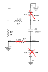
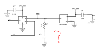
I m using reference design of ADS124S08  but i m using dual channel for RTD ,THERMOCOUPLER measurement .First Page is exactly copied as same as ADS124S08 evaluation design and second page i m using the constant current source externally for RTD .Here also i m also using RTD or thermocouple one at a time for measurement.

I would like to know weather it is ok to use in this configuration. Let me know your feedback .

Tranmitter1.pdf

Regards,

Vipin

  • Hi TI ,

    Can you please let me know your feedback as we are in development phase, need your suggestion to move forward.

    Regards,

    Vipin

  • Hi Vipin,

    Thanks for your patience, yesterday was the weekend in the US.

    I checked your schematic, here is the feedback:

    • I did not any external bias circuit for the thermocouple measurement on both pages, you need either external or internal bias voltage, see the app note: A Basic Guide to Thermocouple Measurements
    • A bias resistor (2.5kohm) is not necessary in a low-side reference of RTD on the 2nd page. If you use it, you may have to pay more attention on component value selection with the reference resistor and the IDAC current because these determine the common-mode voltage on the RTD signal measurement channel, also turn on the internal REFN buffer to increase the input impedance. You may find the information in the FAQ regarding the reference buffer helpful. 
    • You have a power supply ground(GND) and a ground for signal chain circuit (AVSS_GND), but a capacitor (C70) is used between them. I am not an expert of power design, but it would be good for you to check.
    • The diodes in series with the IDAC path can not provide an enough protection. If the protection is needed, check the video here: TI Precision-Labs ADCs: Protecting Delta-Sigma ADC: RTD Overview

    BR,

    Dale

  • transmitter2.pdf

    Hi Dale ,

    Thank you for the Feedback .Here are my response 

    1 We are using internal reference of the ADS124S08 ,hence connected a 10uf at REFCOM pin.

    2.Removed 2.5k Resistor .Secondly ADS124S08 is recommending to disable REFN Buffer in case of Making REFN grounded .Please suggest here what needs to be done .

    3 Removed capacitor and added a 0 Ohm resistor between AVSS and DVDD Ground

    4 Added TVS Diode on all the IO Lines of the Input connector .

    Secondly i would like to know weather i m using external Fixed Current source for RTD ,please suggest me weather it has been connected correctly ,weather it is ok to use it .

    I am switching ON Pull up and Pull down only in case when thermocouple is added for measurement .Is it good approach to use it.

    Last please review again the Modified circuit and let  me know your feedback 

    Regards,

    Vipin

  • Hi Vipin,

    I will look into the details and get it back to you.

    BR,

    Dale

  • Hi Dale ,

    Can you Please let me know your opinion the Attached Circuit .As i m anticipating few more changes that needs to be done .In second page i will be connecting thermocouple on AIN9 and AIN10 i think there will be an issue for thermocouple measurement when i connect it.

    Regards,

    Vipin

  • Hi vipin Mishra,

    Some comments for you:

    1. Dale already mentioned this, but "the diodes in series with the IDAC path can not provide an enough protection." In other words, they don't provide protection against negative overvoltages. We recommend just replacing those diodes with current limiting resistors e.g. 1k ohm, to keep the current into the pin <<10mA. Note that AIN5 is already "protected" in the sense that the 1kohm reference resistor is between the AIN5 pin and the external terminal block. AIN3 is not protected however
    2. You need at least 330nF of bypass caps on the AVDD pin
    3. REFCOM should be directly connected to ground, for some reason you have a cap to ground on this pin. REFOUT should have a cap to ground, which you have, but there is no value associated with this cap
    4. I don't see where the "CJV" output goes, it does not go to the ADC as far as I can tell. I guess you are measuring the temp sensor output with you controller?
    5. Your system is setup to be able to measure 2-, 3-, and 4-wire RTDs. Is that what you want? If you want to just measure a single RTD type you can simplify the circuit of course
    6. On the second RTD with a low-side RREF, you can remove the two caps and short the resistor as shown below. Then make sure the REFN0 buffer is disabled (it is by default)
    7. I don't understand what is the point of the circuit shown in the second image below? Are you trying to create a constant current source? And where is the connection for the second IDAC for the 3-wire RTD?

    -Bryan

  • Hi Bryan ,

    Thanks for the feedback .I have attached the Modified Circuit .

    1 I have added 1Kohm   across AIN3 .

    2.Added 470NF across AVDD .

    3.REFCOM modified now it is directly connecting to GND .REFOUT has 4.7uf Capacitor .

    4.CJV now connecting to AIN11 .

    5. We will give option for 2 and 3 Wire RTD and thermocouple  as well either RTD or thermocouple could be connected at a time for both the connector.

    6.I have changed configuration to high side IDAC measurement now please review and share your thought .Right Now i m using SPDT switch in which it will connect NC and we will have IDAC2 and then it will connect to NO and we will have  IDAC1 so now we have two Measurement .

    7.We are using the constant current source only for RTDS and earlier though i will use single IDAC to measure two times and subtract one measurement from other .Now i have modified it and we are planning to use it same source with a switch for taking two measurement.

    Please share your thought as we are in urgent phase of project .
    Transmitter Reviewed.pdf

  • Hi vipin Mishra,

    Some additional comments for you:

    • As mentioned in #1, you don't need either diode on the IDAC pins, so you can remove the diode on AIN5 as well. AIN5 already has a current limiting resistor due to the 1k RREF.
    • Not sure why you have a 2.5k resistor on the IDAC2 pin, but no additional resistance on the AIN5?
    • As you said, why not just use 1x IDAC for the 3-wire RTD, then take two measurements instead of using 2x IDACs? Using this method you do not need the AIN3 connection on the first RTD, so you can instead connect AIN3 to the high-side of the second RTD circuit (replacing the connection to IDAC2). You can then get rid of the mux, amplifier, and reference components to simplify your system
    • If you only need thermocouple measurements on the second RTD channel because there are no FETs there, you can remove the connection to AIN4 (and associated passives) on the first RTD channel. Since I assume you only need 1x control signal for the FETs i.e. they should both be on or off at the same time, you can swap AIN4 with another GPIO connection on the ADC (AIN8 to AIN11), and then control the FETs using the GPIOs on the ADC. This is just a suggestion, it is not required however
    • I'd consider adding a solid ground plane to your system for all ground nodes instead of having separate analog and digital grounds + a resistor between them. This will be easier to route, and likely result in better performance

    -Bryan