This thread has been locked.

If you have a related question, please click the "Ask a related question" button in the top right corner. The newly created question will be automatically linked to this question.

ADS131A04: Possible cause of low effective resolution of the ADC

Part Number: ADS131A04
Other Parts Discussed in Thread: INA290, INA849

Tool/software:

Hi, 

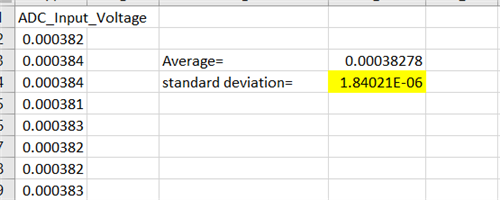
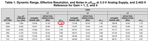
Currently, we are using the ADS131A04 ADC for our high-side current measurement. The inputs to our circuit will go through a current sense amplifier (CSA) INA190A2 which takes data thru a shunt resistor. After calibrating our ADC, we find that our effective resolution is much lower than 24 bits, at best 13 bits and usually lower. We are using the internal regulator of the ADC as the VREF and FullScale value (2.44V). There are no filters active and the OSR is set to be at 4096, the lowest possible sampling rate, 1kHz.

My question:

1) Is the CSA the component that is bottlenecking the ADC effective resolution?

2) If it isn't what are the possible approach that I can take to improve the overall effective resolution.

  • Left out info: Our Vref is unipolar.

  • Hi Kevin,

    You are measuring the effective resolution on the system level. Any components in front of the ADC including the CSA contribute the noise that will degrade the performance including effective resolution.

    First, you need to identify which device/component/circuit contribute more noise than others, a poor layout also could lead to the issue. You can short the ADC input and then take an average of multiple readings across all channels. A minimum 1 second of consecutive readings (~1k samples for 1ksps data rate) are used to calculate the RMS noise for each reading. You can share the raw data and I can check it for you. I assume your circuit does not have any issue.

    BR,

    Dale

  • Hi, Dale!

    Could you kindly clarify on "Short the ADC Input" ? Does this mean I should solder all 4 channels of the ADC inputs to Ground?

    Also, do I need to remove the circuit before the ADC ?

  • Hi Dale,

    I've shorted the ADS131A04 AINP AINN(connected to GND). Below is the channel readings for all 4 channels (after calibration). Do share on how you measure the RMS noise (and other useful parameter). Thanks in advance
    channel2_short_with_csa_VOLTAGE.csvchannel3_short_with_csa_VOLTAGE.csv
    channel0_short_with_csa_VOLTAGE.csvchannel1_short_with_csa_VOLTAGE.csv

  • Hi Kevin,

    I would suggest you to watch the videos from the link to learn more about how to measure the noise and how to calculate the noise in an ADC or data acquisition system: TI Precision labs series: ADC noise measurement, methods and parameters.

    You can short the ADC input first, then move it to the current sense amplifier, then short it on the input of your circuit board in case you have RC filter or other components in front of the amplifier. This procedure can help you identify where the main noise come from and which circuit degrade the performance more than others.

    Since ADS131A04 is a simultaneously-sampling ADC, so you can short the input of each ADC input channel, then analyze the data to check the offset error and the noise on that specific channel.

    I checked the ch2 data in the first excel file you shared, the RMS noise of your ADC circuit is 1.84uV as you can see the result in the following image: 

    I believe you are using Gain=1 on ADS131A04, so the RMS noise at 1ksps and gain =1 should be ~1.82uV as you can see the value highlighted in the table below, so your measured result matches the ADS131A04 datasheet, this indicates that your circuit design of the ADC including coupling, power supply and the layout works as expected

    Next, you can short the amplifier's input and use the same method to check the conversion result from the ADC again, so you can see the noise of the ADC+amplifier circuit.

    BR,

    Dale

  • Hi Dale,

    Thanks for the reply. From the sheet I shared, I was unable to get the same output value as you did, however I calculated the ADC Vrms to be about ~1.90V.

    I've shorted the CSA input to GND (basically trying to get the noise for ADC and amplifier circuit) and found that the measured RMS noise only increased from ~1.90uV to 1.98uV. Based on this, my system's effective resolution should be around 20 bits (with CSA) by calculating using the formula below.

    This doesn't seem to be case with the actual performance of my system. If I was to use the maximum standard deviation at when testing the output vs input, my system resolution would be around 13.88bit.

    Am I missing something? Any pointers will be great. I will go through the TI Precision labs series videos in the meantime. Thanks!

  • Hi Kevin,

    I was checking the data in your first spreadsheet, I do not know why you could not get the same result.

    Can you let me know how you calculate your 13.88bit resolution? Can you share share your RAW data that are original conversion data from the ADC? also let me know what your input signal was when you captured the data. Your schematic will be helpful too.

    BR,

    Dale

  • Hi Dale,

    I'm also averaging and applying stdev formula on the raw data in the csv.

    I calculated the 13.88bit (Channel 0) by getting the maximum std deviation and applying the formula below (From TI's Fundamentals of Precision ADC Noise Analysis)

    I exported my raw data, which is showing in mA (from our workflow) and i calculated it back to voltage by multiplying the INA190A2 gain 50/V and my shunt resistor value of 0.008. So I would be applying V= I (in A) * 0.008 to each raw data.

    Our input system is connected to a calibrated electronic load which draws DC current from 0 to 5A in 0.05A steps. Attached is the results.System linearity results.csv

  • Hi Dale, 

    May I know if you have any update for this?

    Thanks in advance!

  • Hi Kevin Raman,

    The effective resolution is signal dependent. The smaller your signal, the lower the effective resolution. The equation given in the documentation you referenced is the maximum effective resolution you can achieve - in practice the system effective resolution will be lower because every measurement will not use the entire ADC FSR, and reference noise will also need to be considered

    Can you gather the raw data you get from the ADC for a few of the applied currents e.g. 1A, 2.5A, and 4.4A, and provide that to us, similar to how you did for the shorted input test? For this data we will assume the gain is 50 and VREF = 2.44V, unless you state otherwise. We can then perform similar calculations to see what performance you should expect

    -Bryan

  • Hi, Bryan.

    Thanks for replying. My ADC (ADS131A04) is using VREF = 2.44V, with gain x1.

    My analog front end is a shunt resistor 8 milliohms connected to the INA190A2 with gain 50V/V.

    Attached are the files for 1, 3, 5A. Looking forward to your reply.B7_ch1_1A_voltage.csvB7_ch1_3A_voltage.csvB7_ch1_5A_voltage.csv

  • Hi Kevin Raman,

    Thanks, it does seem like this is the performance you should expect from your system. Your amplifier is pretty noisy compared to the ADC, see the input referred noise spectral density plot from the INA290 datasheet below (note this is for the A3 device where G = 100, but I did not see a plot for the G = 50 version). If you assume the A04 bandwidth is ~250 Hz at a data rate of 1kSPS, then that gives you an input-referred noise of 75nV*sqrt(250) = 1.2uVRMS. The ADC noise is 1.82uVRMS at the ADC output, when referred to the input that is 1.82uVRMS / 50 = 36nVRMS, so it is negligible compared to the amplifier noise

    Your maximum applied signal is 0.008ohm * 5A = 40mV

    log2(40mV / 1.2uV) = 15 bits of effective resolution. The data you provided shows an effective resolution of ~13.5 bits at 5A, so this is not too far off (the noise seems to be a bit higher at ~3uVRMS, but maybe that is because we are not looking at the A2 noise response?)

    Assuming there is no other noise source in your system, I'd suggest trying a different amplifier to see if the performance improves. Try the INA849, which is very low noise. This device does not offer the high common mode support on a unipolar supply however

    -Bryan