This thread has been locked.

If you have a related question, please click the "Ask a related question" button in the top right corner. The newly created question will be automatically linked to this question.

ADS1115: ADS1115 LAYOUTING HELP

Part Number: ADS1115
Other Parts Discussed in Thread: OPA140

Tool/software:

Hello All,

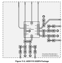
Thank you for your answers in advance. From the component's datasheet I understand that it is recommended to use a RC filter in input pins. But since we are using a low voltage and current sensor, we do not want to load the antenna. Is it possible to directly wire it ? 
  • Hi Berke,

    Can you share more information on the nature of your input signal? What is the bandwidth, and what is the voltage range? How much current can the sensor source?

    In general, I don't believe the RC filter will load your circuit, as its current draw and that of the ADC analog inputs will be minimal once charged up relatively close to the input signal. It would still be a good idea to include one as an anti-aliasing filter. Another option is to buffer and filter the input signal afterwards. 

    Regards,
    Joel

  • Hello Joel,

    Thanks for your quick response. Actually we are trying to capture power signal which is 50 Hz via capacitive coupling. 

    The signal strenght is 150-200mV with 1x probe on oscilloscope and we think that current is in maximum of 100pA levels. We are using ADS1115 in differential mode and FSR of 4Volts to get a high input impedance to achieve an effect like transimpedance amplifier. (we could not implement transimpedance amplifier somehow does not work because of referencing problem).

  • Hi Berke,

    Given the limited signal current, the input current from the ADC may load the input signal, and another concern would be settling of the RC filter. The signal current might not be enough to supply sufficient charge to the filter capacitor close to the input, and keep it stable during the conversion. I don't have too much experience with the exact input you will be utilizing, but my first recommendation given the limitations would be to gain up the signal with a very low input bias current (JFET input) amplifier.

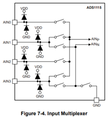
    The leakage current of the internal input protection diodes is definitely a concern. Usually, the input filter capacitor helps as a local source to keep the voltage stable for ADC sampling. 

    Regards,
    Joel

  • Thank you Joel,

    after the jfet, I should use rc filter right? And what about pspice for ti models, can I test those?

  • Yes, the RC filter helps with anti-aliasing and stabilizing the input voltage. This is better described in the datasheet applications section.

    I usually use the TINA SPICE models for modelling, with the ADC equivalent input circuit after the op-amp circuit and RC filter. I've used the OPA140 recently, which may fit your needs, but I would consult with the experts on the amplifiers forum. They should have more specific device recommendations and knowledge on their device's simulation models. 

    Regards,
    Joel