This thread has been locked.

If you have a related question, please click the "Ask a related question" button in the top right corner. The newly created question will be automatically linked to this question.

ADS131M08: Input bias currents

Part Number: ADS131M08
Other Parts Discussed in Thread: ADS131M04

Tool/software:

Hello,
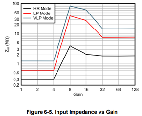
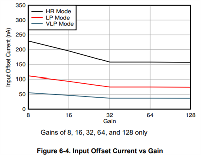
I have a question regarding the input impedance and bias currents of the ADS131M08.
Is it possible to specify the input bias currents of the AINnP and AINnN Pins separately? In the data sheet we have only the sum of both currents.


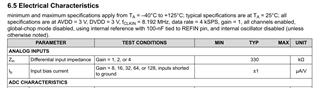
We must use a high impedance resistor divider chain in our application and we have to calculate the influence of the bias currents.

Thank you very much
Ralf

  • Hi Ralf,

    Thank you for your interest in ADS131M08.

    The name of 'Ib' in the table from ADS131M08 datasheet you highlighted actually is the differential input impedance (Zin) in uA/V when the gain is higher than 4. An integrated input pre-charge buffer is enabled at gains greater than 4 to ensure high input impedance at high PGA gain settings. The datasheet should be updated in next revision. The graph in the Figure 6-5 Input Impedance vs Gain reflects the specification of the differential impedance (Zin) that are shown in the table you highlighted.

    For input bias current, you can look at the following table from ADS131M04/M03/M02 ADC datasheet, this table specifies the averaged input bias current on both AINxp and AINxN pin. Figure 6-4 in the datasheet shows Input Offset Current vs Gain, the input offset current is the difference between the input bias currents at the two input terminals.

    BR,

    Dale