Other Parts Discussed in Thread: ADS1299EEGFE-PDK
Tool/software:
Hello, I am having some problems with ADS1299-4 and I need help. I will try to explain the situation I am in as much as possible.
First, the final design will work between 3.3V - 0V.
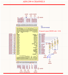
I currently have ADS1299EEGFE-PDK and I am working on a 4 channel eeg device.
I am having difficulty in inferring the bias electrode from the datasheet content. I am trying to get help from the ADS1299EEGFE-PDK structure but this is not enough for me.
I want to use four signal electrodes, one reference and one bias electrode in total.
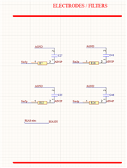
I am connecting RC filters for four channel EEG input and SRB1 pin as reference electrode directly to the electrode.
If I have made a mistake up to this point in schematics, please let me know.
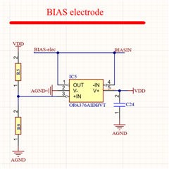
- Now my main problem is which pin should I use to connect the bias electrode?
- Should I connect it directly to the pin or is an additional circuit structure required?
I created a schematic from the ADS1299EEGFE-PDK datasheet reading, but I am not sure if it is correct.
I shared the schematic images below, thank you in advance for your help.