This thread has been locked.

If you have a related question, please click the "Ask a related question" button in the top right corner. The newly created question will be automatically linked to this question.

ADS1298ECGFE

Other Parts Discussed in Thread: ADS1298, ADS1298ECGFE-PDK

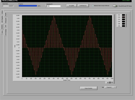
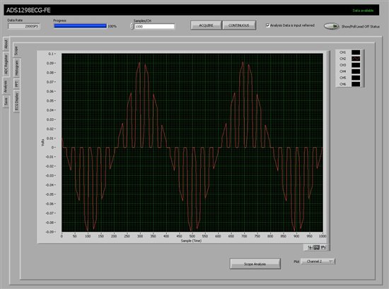
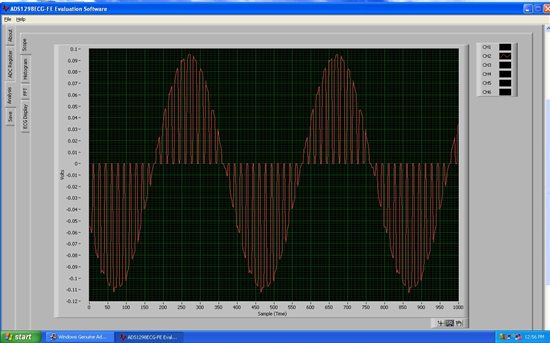
I am feeding to the channel 2, a sine wave with frequency of 5Hz. When I read back from the board, everything is OK, except that the sine wave is multiplied by a square wave with a frequency of around 1KHz. 

Why is this happening? 


  • Hi Masoud,

    Welcome to the forum!  Can you tell us how you have the power to the ADS1298 set up (bipolar +/-2.5V supplies or 0-3V)?  Could you also grab a screen shot of the ADS1298 register tab so we can review how you have the device configured?

  • I haven't changed anything much from the defaults. I have attached a screen shot of the board to look at the jumper locations and also the register map. For power supply, I have just used the DC-adapter that came with the board and I connected that to the mother board. 

    I am feeding signals to RA and LA and the rest of leads (LL,V1,etc) are grounded with the ground of signal generator. 

  • Hi Masoud,

    Looks like from your register settings that you are running the converter at a data rate of 4kSPS and seeing a 1KHz signal on top. Could you go in and turn off all of the lead off bits and double check that you do not have AC lead off enabled? The AC leadoff excitation signal would show at 1KHz if enabled. Your register settings look like you do not have it enabled but I figured I would bring it up just in case.

    Regards,

    Tony Calabria

  • I am sorry, I miscalculated the frequency, if you see from the waveform, the square on top of my signals has a frequency of around 100Hz. I have turned all of those bits and also have attached the screen shot of my settings + what I get when I feed it a ramp with frequency of 5Hz while sampling at 2000SPS  

    I still don't know what is going wrong! 

  • I missed the screen shot of lead-off page: 

  • Hi Masoud,

    Please verify all of your power supply voltages.  Monitor TP 5, TP13 and TP6 relative to TP1 and let me know what you have.  I see similar conversion results if I do not have the correct Vss voltage supplied to the ADS1298:

  • Thanks for your response! TP5, TP13 and TP6 are 3V, 2.5V, -2.5V respectively. TP3 is also -2.5V. All the voltages listed in the table.1 are also correct. Am I supposed to change any voltage from the default to make the board work? Do you have any other suggestion? 

    Best, 

    Masoud

  • Hi Masoud,

    Relative to TP1, the reference (TP3) should read about -0.1V if you have the internal reference configured for 2.4V (your CONFIG3 at 0xDC implies this is how you have the reference set).  The reference is relative to the AVss supply, so when you measure from ground (TP1) you should see -2.5 + 2.4 = -0.1V.  With the reference set for 4V, relative to TP1 you should see -2.5 + 4.0 = 1.5V.  If the reference buffer is powered down, or if you just powered up the board without loading the software, you would see -2.5V at TP3.

  • Hi Tom, 

    I see -2.5V on TP3 after I power up the board. When I connect it to the PC, the voltage becomes -0.1V with reference voltage of 2.4 and 1.5V as you have suggested. However, i still have the same problem. 

    I thought that the problem was with the board, so I ordered a new one to replace my board and I tested it today. I got the same type of error. Let me say what I did with the board exactly. 

    1- All jumpers are in their default positions. I power up the board with the supplied adapter. 

    2- I connect the board to PC and then I check whether the channels work or not in the test mode. All the channels work fine in the test mode. 

    3- Now, I connect the RA pin of the connection to the positive electrode of signal generator and LA pin to the positive electrode of signal generator. My goal is to give signal only to channel 2, as the difference between RA and LA (Lead I). 

    4- I connect all other pins of the connector (V1, V2, ect) to the negative electrode of signal generator. The settings (registers) are the same as the one I mentioned above. 

    After all this step, I get the same familiar errorouns signal from the board. 

    Have I done anything wrong? Do you have any idea to fix this issue? 


    Thanks, 
    Masoud  


  • Hi Masoud,

    Take a look at the schematic (Sheet 1 of 5) in the back of the ADS1298ECGFE-PDK Users Guide, assuming you have your (+) signal tied to pins 9 and 10 of J1; follow that through to the ADS1298 input (Sheet 2 of 5).  The ECG_LA and ECG_RA map to the two shunt jumpers on JP32, which feed directly into IN2P and IN2N.  Technically you should be shorting these pins together from the description above and you should actually be getting a flat line (0V) in the scope display. 

    Try removing both shunt jumpers at JP32 and clip your signal generator onto pins 2 and 4, which are the two pins closest to the ADS1298.  Let us know if that cleans up the scope display at all.

  • Hi Tom, 

    I did as you suggested; however, I got the same type of error. I looked at the FFT page and I noticed huge spikes at all the 60Hz harmonics. What I did next was connecting the ground of signal generator directly to the ground of the board (the picture). The connection completely removed the interference and the signal became crystal clear. 

    I don't know why this connection rejected the huge power supply interference which looked light short circuit, do you know? Anyhow, I want to measure the electric potential between the right hand left hand (lead I) and it seems to be impossible to do it with just two cables as I have hoped. The signal is just  lost in noise and interference. Do you think having right leg drive would be the only way to do it?

    Thanks a lot!

    Masoud 

    P.S. Now I see that all commercial ECG recorders that have only two leads work with just batteries and do not have AC adapters. Is it a coincidence? Would using batteries instead of AC adapter remove the interference? 

    P. P.S. The user guide at the ADS1298ECGFE-PDK is outdated (it is for rev-A). Although, I easily found the newest version in here

  • Hi Masoud,

    I'm happy to hear you found the problem!  We've been using various Stanford Research and Agilent signal generators to test the boards and I've never seen this sort of behavior from that equipment.  Using batteries definitly helps reduce 50/60Hz pickup from the power line, but you can still get pickup from everything else around you - lights, equipment, etc.  The RLD helps as does good shielding of the cables.