This thread has been locked.

If you have a related question, please click the "Ask a related question" button in the top right corner. The newly created question will be automatically linked to this question.

BP-DAC11001EVM: BP-DAC11001EVM

Part Number: BP-DAC11001EVM
Other Parts Discussed in Thread: DAC11001A

Tool/software:

Hello, 

I am trying to connect BP-DAC11001EVM with ESP32. But somehow, I cannot see any output at the DAC side. My ESP 32 is establishing the communication with the DAC. But I don't see any voltage at the output. I have attached the code below that I am using. Please let me know what the issues could be. 

Code:

import machine
from machine import Pin, SPI
import math
import time

# SPI Configuration
spi = SPI(1, baudrate=1000000, polarity=0, phase=0, sck=Pin(18), mosi=Pin(23))
cs = Pin(5, Pin.OUT)       # Chip Select for DAC
ldac = Pin(16, Pin.OUT)    # LDAC for DAC

cs.value(1)
ldac.value(1)

# Function to send 20-bit data to DAC (in 24-bit format)
def send_to_dac(cs, value):
    cs.value(0)
    spi.write(value.to_bytes(3, 'big'))
    cs.value(1)

# Generate single-phase sine wave
def generate_sine_wave(frequency=50, amplitude=1.0, sample_rate=1000):
    step = 0
    while True:
        # Generate a sine value between 0 and full-scale (20-bit)
        sine_val = int((amplitude * (math.sin(2 * math.pi * frequency * step / sample_rate) + 1)) * ((2**20 - 1) / 2))
        send_to_dac(cs, sine_val)
        time.sleep_us(10)  # Delay before toggling LDAC
        ldac.value(0)
        time.sleep_us(10)  # Delay after toggling LDAC
        ldac.value(1)
        step = (step + 1) % sample_rate
        time.sleep(1 / sample_rate)

# Start generating the signal
generate_sine_wave(frequency=50)
  • Hello Sanjana, 

    Try changing your SPI clock/phase to 0/1 or 1/0 so the data is shifted on the rising edge and captured by the DAC on the falling edge. 

    If this doesn't work, please share how you have wired up the ESP32 to the EVM, what supplies you have wired up to the EVM, and the jumper settings on the EVM. 

    Best,

    Katlynne Jones

  • Hello, 

    DAC11001A Pin

    ESP32 GPIO

    Function

    SDIN (32)

    GPIO23

    SPI MOSI

    SCLK (31)

    GPIO18

    SPI Clock

    SYNC (33)

    GPIO5

    Chip Select (CS)

    LDAC (18)

    GPIO16

    Load DAC

    Power Supply Routing

    To ensure safe and stable operation:

    • Analog Power:
      • J12 (VCC): +12 V
      • J13 (VSS): -12 V
    •  


    • Digital Power:
      • J14 (VDD): +5 V (for DAC internal logic) from 5V0 ESP
      • J15 (VIO): +3.3 V from matches ESP32 3v3
      • Jumpers:
        • J11: DVDD from VDD (2-3)
        • J16: IOVDD from VIO (2-3)

    All grounds (AGND, DGND, REFGND) must be tied to the same 0V reference, which should be shared with the ESP32 ground.  

    Above are the connections.

    Code that I am using is 

    import machine
    from machine import Pin, SPI
    import math
    import time

    # SPI Configuration
    spi = SPI(1, baudrate=1000000, polarity=0, phase=0, sck=Pin(18), mosi=Pin(23))
    cs = Pin(5, Pin.OUT)       # Chip Select for DAC
    ldac = Pin(16, Pin.OUT)    # LDAC for DAC
    cs.value(1)
    ldac.value(1)

    # Function to send 20-bit data to DAC (in 24-bit format)
    def send_to_dac(cs, value):
        cs.value(0)
        spi.write(value.to_bytes(3, 'big'))
        cs.value(1)

    # Generate single-phase sine wave
    def generate_sine_wave(frequency=50, amplitude=1.0, sample_rate=1000):
        step = 0
        while True:
            # Generate a sine value between 0 and full-scale (20-bit)
            sine_val = int((amplitude * (math.sin(2 * math.pi * frequency * step / sample_rate) + 1)) * ((2**20 - 1) / 2))
            send_to_dac(cs, sine_val)
            time.sleep_us(10)  # Delay before toggling LDAC
            ldac.value(0)
            time.sleep_us(10)  # Delay after toggling LDAC
            ldac.value(1)
            step = (step + 1) % sample_rate
            time.sleep(1 / sample_rate)

    # Start generating the signal
    generate_sine_wave(frequency=50)

    My aim is to get bipolar sine signal at the output of the DAC.


  • Hello Sanjana, 

    Did you try your SPI clock/phase to 0/1 or 1/0 so the data is shifted on the rising edge and captured by the DAC on the falling edge? Eithout the correct SPI format, not writes to the DAC will go through. You should start by confirming you can update the DAC output at all and then move to the sine wave code.

    Each DAC update requires 4 bytes, not 3. As there is an address byte and three data bytes. 

    Best,

    Katlynne Jones

  • Hi, 

    Can you please elaborate more about this. What changes I need to do in my code. Actually, I can see the output at LDAC of BP-11001DAC. From this I concluded that ESP32 and DAC module are configured and are communicating. Further I was expecting to some output across the output of BP-DAC11001 EVM. But was unable to see any output. If you could elaborate about how I can get the output across the DAC would be really great. Also about phase and clock , can you elaborate more about it? What exact changes you want me to make?

    Regards,

    Sanjana Bhalekar

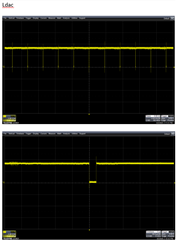
  •     This the waveform I can see across LDAC pin on EVM DAC11001. I just wanted to let you know the output. 

    Regards

    Sanjana Bhalekar

  • Hi Sanjana,

    LDAC is not an output from the DAC, it is an input. The DAC captures data on the SCLK falling edge meaning that your MCU needs to shift it out on the rising edge. This is done with the phase and polarity settings in your SPI initialization settings at the very beginning of your code. You can set SPI polarity/phase to 0/1 or 1/0 so the data is shifted on the rising edge and captured by the DAC on the falling edge. 

    Best,

    Katlynne Jones