This thread has been locked.

If you have a related question, please click the "Ask a related question" button in the top right corner. The newly created question will be automatically linked to this question.

ADS124S08: how to interface 3 NTC with ADS124S08?

Part Number: ADS124S08
Other Parts Discussed in Thread: ADS1220

Tool/software:

Dear product line application engineer,

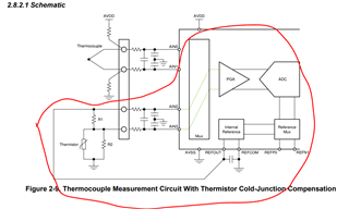
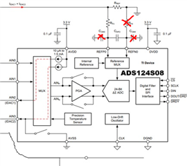
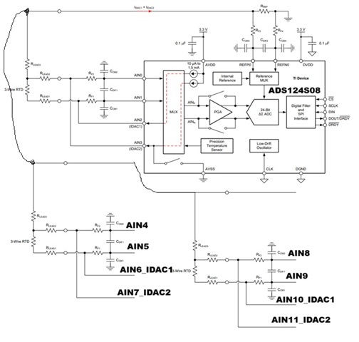
I want use ADS124S08 to interface with 3 NTC thermistors to monitor temperature of SIC-MOSFET module. the schematic as below figure shows. is it workable? you have my big thanks.


regards,

Bill

  • Hi Bill Xu,

    Can you please help respond to my question in the Notes section of the Thread Tracking Toolkit? We will review your questions while we wait for your response

    -Bryan

  • Hi, Bryan

    I visited my customer last Thursday which design high voltage power supply for x-ray/CT system. during the visiting, customer ask us how to monitor the IGBT/SIC-MOSFET temperature to improve system reliability. then I study the IGBT/SICMOSFET and find there had integrated 1 or 3 NTCs in the module.

    my first idea is to use ADS1220 to monitor IGBT/SICMOSFET temperature, however, for a 3-phase SIC-MOSFET/IGBT module , there has 3 NTCs, these means that I need 3 PCs ADS1220 to monitor modules temperature. this will cause cost increasing and large PCB area. So I want to try ADS124S08 for cost down and compact design.


    I feel this is a general issues in electrical car since SIC-MOSFET was widely used in electrical car to drive motor. but I could not find any application notes to monitor SIC-MOSFET temperature in ti.com. thanks for your supporting.

    regards,

    Bill

  • Hi Bill Xu,

    The ADS124S08 can definitely be used to measure multiple thermistors

    But the setup you have shown in your original post seems more like it would be used for RTDs, not thermistors. I would have expected a voltage-excited circuit similar to the one I have circled below. In this case, the REFOUT pin on the ADS124S08 is used to bias the resistor divider, and the ADC measures either the top (differential) or bottom (single-ended) resistor.

    The VREF on the ADS124S08 can drive up to 10mA, so that should be more than sufficient to bias 3x resistor dividers. It is also possible to use current excitation, but the current generally needs to be pretty low (10uA?) because the NTC resistance can be very high (nominally maybe 10k, and then can increase to 100kohm at the temperature extremes)

    Let me know if you have any questions about this

    -Bryan

  • Hi, Bryan,

    use internal reference to build an resistor divide is workable. but the function between resistance of thermistor with bias resistor is non-linear. in actual application, customer may use MOSFETs without integrate NTS resistors, then potential long wire need compensation. the third issues is an general ADC can easy to test divider voltage, this will make our solutions has lots of competitors and no much benefits. so, I feel that my original idea should more attractive for customers compare competitive solutions.

    do you think that the orginal solutions can work or not? is there any risks that I'm not considered? thanks.

    regards,

    Bill  

  • Hi Bill Xu,

    The RREF resistance needs to be larger than the NTC resistance for your proposal to work. Do you know what the NTC resistance range is that needs to be measured? This will help you determine what the maximum current can be. It is possible that the ADS124S08 does not offer a small enough current to bias the resistor divider

    Let me know what the resistance range is for the NTC, then we can figure out if your solution will work

    -Bryan

  • Hi, Byran

    the resistance range is 300ohm~10kohm. thanks.

    regards,

    Bill

  • Hi Bill Xu,

    This should be possible. If you assume that RREF is maybe 12kohm, that's 12kohm + 10kohm (max) = 22kohm. Assuming the ADC AVDD = 5V, and the compliance voltage is AVDD - 04V = 4.6V, that's a maximum current of 4.6V / 22kohm = 210uA. The ADS124S08 can output 100uA, so that should be doable.

    Of course the output signal will be very small when the NTC = 300ohms compared to when the NTC = 10kohm using IDAC = 100uA.

    Do you really think the lead resistance on the NTCs will be significant enough to require lead compensation using 2x IDACs?

    -Bryan

  • hi, Bryan

    when NTC resistance equal 300ohm, we can adjust internal PGA's gain to improve the accuracy. Am I right? in actual application, customer designer potential varies from case by case. this means that in some application, wire resistance maybe neglectible. but some application could not neglect. So, I feel it is good to keep lead compensation. BTW, do you think that my original scheme workable and no errors? thanks.

    regards,

    Bill 

  • Hi Bill Xu,

    Yes you can use a larger gain for smaller signals, but of course you need to know what the signal is to be able to increase the gain. One possible way to detect this would be to use a large gain, and if the signal saturates i.e. you get a full-scale output, you reduce the gain and try again until the output is no longer saturated. I'm not sure if you have other ideas to implement this dynamic gain scaling, typical RTD/NTC measurement systems use a fixed gain for all measurements for a specific RTD/NTC type

    Understood about the lead resistance

    If you use the circuit as shown with the ADS124S08, you don't actually need the components crossed out in the image below. Otherwise this looks just like a 3-wire RTD measurement.

    -Bryan

  • Hi, Bryan

    yes, I try to use a 3 wire RTD for lead compensation. does the original circuit runable? could you please propose a circuit between ADS124S08 and three 3-wire NTCs? big thanks.

    regards,

    Bill

  • Hi Bill Xu,

    As mentioned in my last post, your circuit looks correct assuming you remove the components I crossed out in the image. This is now just a 3-wire RTD measurement, but with an NTC.

    -Bryan

  • hi, Bryan

    one thing: why need remove the resistor and filter capacitor? I'm not get your idea. could u please a little explain? I feel it should be workable if not remove the resistor and filter capacitor. thanks.

    regards,

    Bill

  • Hi Bill Xu

    Please read this post for more information: https://e2e.ti.com/support/data-converters-group/data-converters/f/data-converters-forum/886352/faq-ads124s08-when-should-i-enable-disable-the-external-reference-buffers

    Note that this information is specific to the ADS124S08

    Also, you can trust what we say, we are the experts Slight smile

    -Bryan

  • hi, Bryan

    thanks for explain. got it. 

    yes, I absolutly trust what you said! but I also need get the root reason that I'm not got. Slight smile

    regards,

    Bill