This thread has been locked.

If you have a related question, please click the "Ask a related question" button in the top right corner. The newly created question will be automatically linked to this question.

ADS8556: Hardware Mode, Parallel Interface, Irregular conversion values

Part Number: ADS8556

Tool/software:

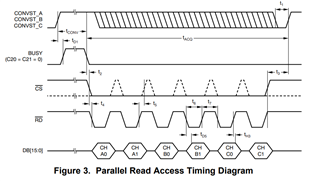
So i am converting six channels.
Rising edge Convst for A B C.
Waiting for BUSY falling interrupt
Setting CS Low
Setting RD Low and reading CH1
Setting RD high and then low and reading CH2 and so on.

Internal Ref with +-4Vref Range selected.

So when i apply 3.3V, I get around adcOutput = ~27340
And when i apply 5V, I get around adcOutput = ~24700

To get float this is what i am doing:
adcValue = int16_t(adcOutput)

float voltage = adcValue * 10/32767;

My question is why i am getting this wrong adcoutput?

And just to mention here that i am doing this on prototype before finalizing the pcb, i have a uC development board and I just connected wires for parallel to adc. And similarly adc is on lqfp64 to dip converter and then wires use to supply voltage and define states for hardware interface. Of course i have placed all the necessary cap on the converter for adc.

And I am not using any RIN or CIN (low pass) to input voltage. Just directly applying voltage to channel pins.

  • Hi Zain,

    Thanks for your post. A few questions:

    1. Can you probe HVDD, HVSS, AVDD, BVDD, and VREF/REFIO and let me know what the voltages are?
    2. Is your 3.3V and 5V input signal DC or AC? If AC, what is the frequency?
    3. Are you in hardware or software mode? Have you made any changes to the control register? Can you let me know what changes, if any?
    4. Could you send me a schematic to see your pin connections?

    Best regards,

    Samiha

  • 1. +15V, -15V, 5V, 3.3V, 2.5V
    2. Its a dc signal
    3. Hardware mode, I didn't access the control register.
    4. I don't have schematic as I just developed a prototype by giving connections on paper to the stuffing team. And I have verified connections several times.

  • Hi Zain,

    Okay. Are you holding the PAR pin low to use parallel mode? Are you operating in 16bit or 8bit parallel interface, that is, is your WORD/BYTE pin set to high or low? Are you in internal clock mode?

    Also, when you short the input to ground, what code do you see? When you apply 1V, what code do you see?

    Could you show me a logic analyzer or oscilloscope capture of the following signals, CONVST, BUSY, /CS, /RD, and one or two of your data output signals.

    Best regards,

    Samiha

  • For someone who is going to do this in future.
    For reading parallel data I used following in stm32:


    adcValue = GPIOC->IDR << 8 | GPIOA->IDR;

    IDR is 16 bit register so it was giving me everything from pa0-pa15, my data db0-db7 is from pa0-pa7, So I was doing OR from pa8-pa15 with my valid db8-db15 data that I read from pc0-pc7. I just discarded the upper bits and its working now:

    adcValue = GPIOC->IDR << 8 | (GPIOA->IDR & 0xFF);