This thread has been locked.

If you have a related question, please click the "Ask a related question" button in the top right corner. The newly created question will be automatically linked to this question.

ADS1263: What is bandwidth of analog inputs?

Part Number: ADS1263

Tool/software:

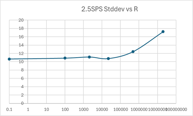
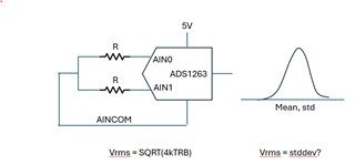
I am using the ADS1263 to measure thermal noise across a resistor. I have 5V analog supply with internal 2.5V Vref for REFP and REFN. I configure sampling at 2.5 SPS with sync1 filter. I configure the level shift output on AINCOM and connect two resistors of value R differentially from AINCOM to AIN0/AIN1. Then I measure 5K samples and determine the standard deviation S. I convert that to bits B by: B = log2(S).

First question: From the datasheet, noise should be 0.121uVrms which is 0.121E-6/(1/2^32) = 520 lsbs = 9b. It looks like from my data I see a noise floor at ~11b. Am I calculating this incorrectly? Why might I see 4x higher noise than datasheet? Would it be power supply noise on AINCOM from the level shifter?

Second question: If I want to estimate the expected Vrms of the thermal noise I need to know the bandwidth of the inputs to know how much noise aliases right? I see with PGA bypassed the differential input impedance is spec'ed at 40Mohm. What is the capacitance?

Third (bonus) question: If I want maximum ADC noise I sample at 38.4Ksps with sync1. I assume some of that noise is device noise (thermal, flicker, etc) and some is quantization noise. Is that correct? I see repeatedly in literature that quantization noise is treated as white which makes sense from a power spectrum point of view. But, what can be said about the randomness or entropy of this noise. Technically it is deterministic right?

Best,

Rachael Parker

  • Actually, there is a mistake in my calculation. Should be:

    0.121uVrms which is 0.121E-6/(5/2^32) = 104 lsbs = 6.7b so my data is even farther off than i thought. Like 16x.

  • Hi Rachael Parker

    What signals are you actually measuring? Are you measuring the difference between the signal chain shorted inputs (PGA+ADC) noise and with a resistor installed (resistor noise + PGA + ADC)? What is the point of the VBIAS signal then? It would help to have a block diagram or even a schematic

    The ADS1263 VBIAS is not a low noise output, so it is very possible you are adding noise to your system by using this feature

    The system bandwidth will be dominated by the ADC digital filter, especially at 2.5 SPS. You can see from Table 9-4 that the sinc filter BW at these settings is 1.1 Hz

    At 38kSPS, the ADS1263 noise will be mostly due to quantization. Quantization looks broadband in the frequency spectrum when measuring an AC signal. For DC signals, quantization just looks like an offset error, assuming the input signal is truly DC i.e. never changing. 

    -Bryan

  • Here is my experiment:

    My application needs to be able to know how much noise is coming from the ADC and how much is from the DUT. So as an experiment I am trying to measure Johnson/Nyquist (thermal) noise across a resistance. Because it is small signal I am following datasheet guideline to use the level shifter to provide a common mode.I have the PGA bypassed so I am measuring resistor noise plus ADC.

    If the VBIAS is not low noise, is there a better way to do this experiment?

    I understand that the digital filter sets the system bandwidth, but i am interested in understanding the BW of the AIN0/AIN1 inputs for the case where I do not use an anti-aliasing filter. I believe that is what I should use for the B term in the Vrms calculation. I am a little unsure of this.

    regarding thermal noise vs quantization noise, your reply is opposite what I got from this video from TI that I found last night:

    https://www.ti.com/video/6242062186001

    This video suggests that the ADS1263 noise is mostly thermal. What am I missing?

    Thank you,

    Rachael

  • Hi Rachael Parker,

    I don't know much about measuring resistor noise, the only method I have ever seen is to measure the intrinsic noise of your system by shorting the inputs, then measure the resistor "output" when it is connected to the inputs (seems like it was floating), and then subtract the two to determine the resistor noise. But I don't know anything about the efficacy of this approach, just that it exists.

    For your specific system you could also try using a low noise reference to set the bias point instead of VBIAS: https://www.ti.com/product/REF80

    The resistors will see the digital filter (system) bandwidth at the point at which you measure the noise (the ADC output), so I am not sure I understand your comments about the inputs

    As you can see in the first image below, the quantization noise is shaped by the delta-sigma modulator and pushed out to higher frequencies. For most data rates the filter bandwidth is low enough that all of that noise gets removed. This is shown in the second image. However, you can imagine that if the filter BW was high enough, all of that quantization noise would be let into the system, and would dominate compared to the ADC thermal noise. This is what happens at the highest data rate using the ADS1263: the device effectively becomes a 16<-bit ADC, which is where quantization noise is more prevalent.

    -Bryan