Other Parts Discussed in Thread: MUX36S08,
Tool/software:
Hello,
I am currently a student studying PIC microcontrollers.
I'm working on a project and having difficulties with the SPI communication part, so I’m writing to kindly ask for your advice.
First of all, thank you in advance for your help.
Current Hardware Configuration
8-channel 4–20mA current sensor inputs
Each channel’s current is converted to voltage through a 250Ω resistor (confirmed working)
Channels are selected using a MUX36S08, controlled via photo-couplers from the MCU
The selected voltage is read by an ADS8689, which sends the digital voltage to the MCU via SPI
The MCU sends the sensor readings to the terminal via RS232 communication
Use mcu pic16f15356
Current Terminal Output(current code)
<MUX36S08 + ADS8689 Start testing>
CH0 = 0
CH1 = 0
CH2 = 0
CH3 = 0
CH4 = 0
CH5 = 0
CH6 = 0
CH7 = 0
All channels are currently showing a value of 0.(Sensor 4ma is input to channel 1)
What I’ve Checked
Current input from the sensors → voltage after 250Ω resistor confirmed
MUX36S08 control is working (voltage output per channel confirmed)
Entire hardware power supply is operating normally
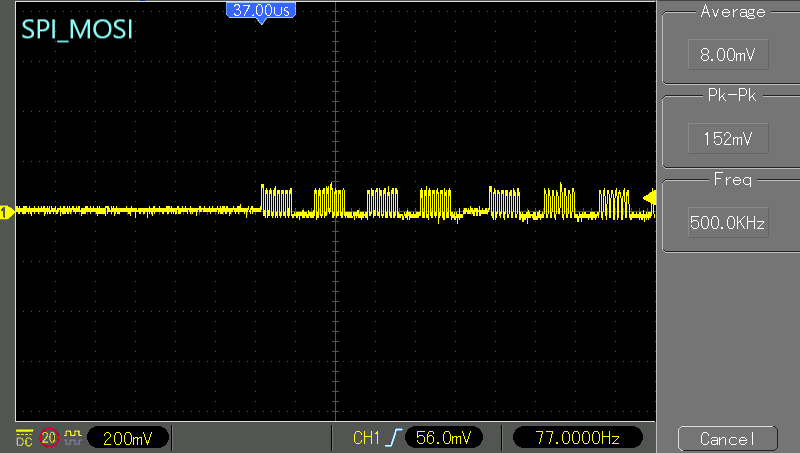
SPI signal measurements via oscilloscope:
CS: pk-pk 4.6V / Avg 2.20V
CLK: pk-pk 4.4V / Avg 1.20V
MISO: pk-pk 1.92V / Avg 160mV
MOSI: pk-pk 180mV / Avg 12.0mV → too weak, suspected issue
ADS8689 pin 9(RST) is pulled up to 3.3V with a resistor, but is not connected to the MCU
Current Issue
Although RS232 communication appears to be working, I am not sure if the issue lies in the SPI communication or elsewhere.
I would sincerely appreciate it if you could review my code and let me know if there are any corrections or improvements needed, especially regarding SPI communication and initialization.
Could the ADS8689 RST pin be the problem??
Thank you very much for your time and support.
#include <16F15356.h>
#include <stdint.h>

#device ADC=10
#use delay(internal=8MHz)

//Hardware SPI settings
#pin_select SCK1 = PIN_C3
#pin_select SDI1 = PIN_C4  // ADS8689 MISO
#pin_select SDO1 = PIN_C5  // ADS8689 MOSI
#use spi(MASTER, SPI1, MODE=0, BITS=8, BAUD=500000, STREAM=SPI_1)

//RS232 Settings
#pin_select U1TX = PIN_C6
#pin_select U1RX = PIN_C7
#use rs232(baud=9600, xmit=PIN_C6, rcv=PIN_C7, stream=UART1)

//Chip Select Pin
#define ADS8689_CS PIN_C2

// MUX36S08 Control pin definition
#define MUX_A0  PIN_A0
#define MUX_A1  PIN_A1
#define MUX_A2  PIN_A2

// MUX Channel selection function(0-7)
void MUX36S08_Select(uint8_t ch)
{
   output_bit(MUX_A0, bit_test(ch, 0)); // A0
   output_bit(MUX_A1, bit_test(ch, 1)); // A1
   output_bit(MUX_A2, bit_test(ch, 2)); // A2
}

//ADS conversion value reading function
uint16_t ADS8689_ReadADC()
{
   uint8_t msb, lsb;

   output_low(ADS8689_CS); delay_us(1);

   //Send NOP command
   spi_xfer(SPI_1, 0x00);
   spi_xfer(SPI_1, 0x00);
   spi_xfer(SPI_1, 0x00);
   spi_xfer(SPI_1, 0x00);

   output_high(ADS8689_CS); delay_us(5);

   //Receive transformation values in the next frame
   output_low(ADS8689_CS); delay_us(1);

   msb = spi_xfer(SPI_1, 0x00);  // D[31:24]
   lsb = spi_xfer(SPI_1, 0x00);  // D[23:16]
   spi_xfer(SPI_1, 0x00);        // D[15:8] (ignore)
   spi_xfer(SPI_1, 0x00);        // D[7:0]  (ignore)

   output_high(ADS8689_CS); delay_us(1);

   return ((uint16_t)msb << 8) | lsb;
}

void main()
{
   uint8_t ch;
   uint16_t adc;

   delay_ms(100);
   printf("\r\n<MUX36S08 + ADS8689 Start testing>\r\n");

   while(TRUE)
   {
      for(ch = 0; ch < 8; ch++)
      {
         MUX36S08_Select(ch);
         delay_ms(10);  //wait for stabilization

         adc = ADS8689_ReadADC();  //Read conversion value
         printf("CH%u = %lu\r\n", ch, adc);

         delay_ms(500);
      }
   }
}


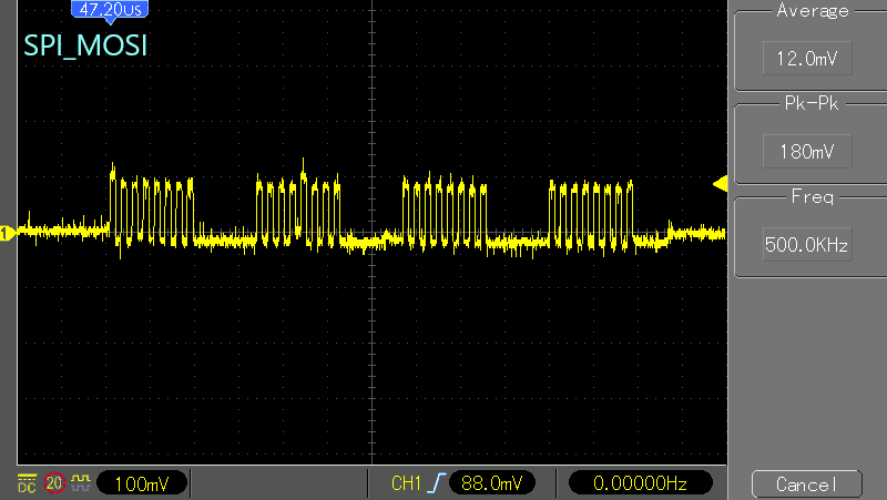
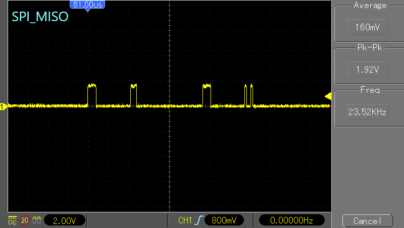
SPI_MOSI SPI_MISO
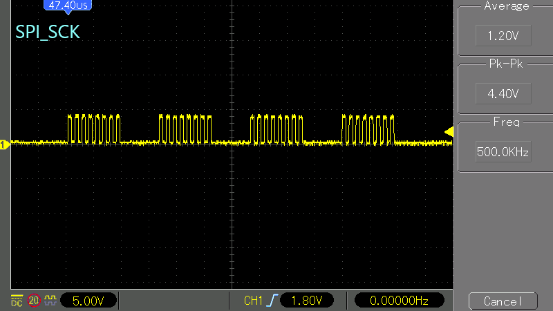
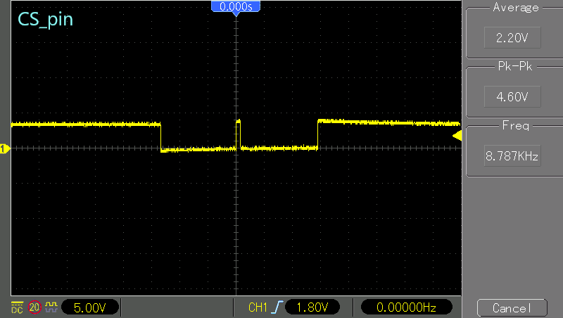
SPI_SCK CS_pin