This thread has been locked.

If you have a related question, please click the "Ask a related question" button in the top right corner. The newly created question will be automatically linked to this question.

TPL1401: Cascading connections

Part Number: TPL1401
Other Parts Discussed in Thread: DAC81404, DAC53204

Tool/software:

Hello,

I am planning on designing a voltage divider network from 4 TPL1401 in series. It is mentioned in the datasheet that device operates in the voltage range of 1.8-5.5V. 

My design would require would 4 of them in series with a total supply voltage of 8-15V, so each TPL1401 would have a voltage of 2-3.75V, according to datasheet it should work.

My query is that is it possible to connect several TPL1401 in series like a bank of resistor dividers.

Thanks

Vaibhav Khatri

  • Hi Vaibhav,

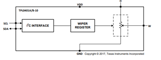
    Can you draw how you plan to connect them in series along with the intended supply voltages? I might be misunderstanding your intended circuit, but the TPL1401 is a buffered output digipot, so the output is not directly connected to the internal resistor ladder.

    This could work for our unbuffered digipots like TPL0401, as long as you ensure the voltage across each digipot is kept below the maximum voltage ratings. 

    Another key point if you plan to use this method with different supply levels is that the I2C bus for each device needs to be shifted accordingly. 

    Best,

    Katlynne Jones

  • Hello,

    I intend to use TPL1401 in this manner:

    https://tinyurl.com/3ev3j8fe

    This is a draw.io image.

    My intended application is to simulate a four channel voltage divider which can provide four different output voltage channels from a single supply of 9-14V.

    I went through the datasheet of TPL0401, it seems like it can be used for my application, but I am not sure how would I establish I2C communication. 

  • Hi Vaibhav,

    Thanks for the drawing. This will not work as the internal resistor string is not directly connected to VDD and GND like a traditional digipot. You won't get a stacked resistor divider like you are expecting. 

    This could work for something like the TPL0401 like I mentioned, but you would have to ensure that even on startup the devices are not seeing a differential voltage (VDD-GND) above the maximum ratings. 

    For the I2C, you'd need to level shift the signals for each device to reference the VDD and GND of each device. 

    Can you share your end application and requirements? Maybe we can brainstorm other methods that could also work. 

    Best,

    Katlynne Jones

  • Hello Katlynne,

    My end application here is to emulate a battery pack and its individual cell voltages. Traditionally I have been using a simple voltage divider to generate 4 different voltage levels by providing a voltage of 14V and tapping at each connection point of consecutive resistors to obtain 14V, 10.5V, 7V and 3.5V.

    The problem with this solution is that you cannot change the voltage at each tapping point without changing the resistance or varying the supply voltage at top resistor. I want to automate this, so I thought of using cascaded digipots. 

    But as you mentioned, I would require some logic level shifting on the I2C line, for that I have one more solution, take a look at this:
    https://tinyurl.com/2fhszzb4

    Let me know if this idea would work or if you have some other solution let me know.

    Thanks

    Vaibhav

  • Hi Vaibhav, 

    That should solve the I2C issue. 

    Do you need to use one resistor divider supply with tap points connected to your 9-14V? Or could you use a 4-channel DAC to get 4 programmable voltage outputs? We still don't have many DAC options that will accept a 14V reference, but you could divide down this reference (or use a DAC with an internal reference) and then use 4 external op amps to gain back up the outputs. Something like the DAC53204 could work for that. DAC81404 could work with

    A DAC and 4 op amps might be simpler than the I2C level shifters. 

    Best,

    Katlynne Jones

  • Hi Katlynne,

    I need to use one resistor divider with tap points to obtain all 4 voltages. 

    I can use a DAC with 4 op-amps to generate all 4 voltages but the problem is that I can't push the current in the op-amp's output pin to simulate balancing. I need a resistor network only, no active circuitry. 

    Thanks,

    Vaibhav

  • Hi Vaibhav, 

    In that case, the digipot and I2C level shifters would be the best option. 

    Best,

    Katlynne Jones

  • Thanks Katlynne.