This thread has been locked.

If you have a related question, please click the "Ask a related question" button in the top right corner. The newly created question will be automatically linked to this question.

ADS8689W: Resistor Question and Schematic Check

Part Number: ADS8689W
Other Parts Discussed in Thread: ADS8681WEVM-PDK

Tool/software:

Hello all,

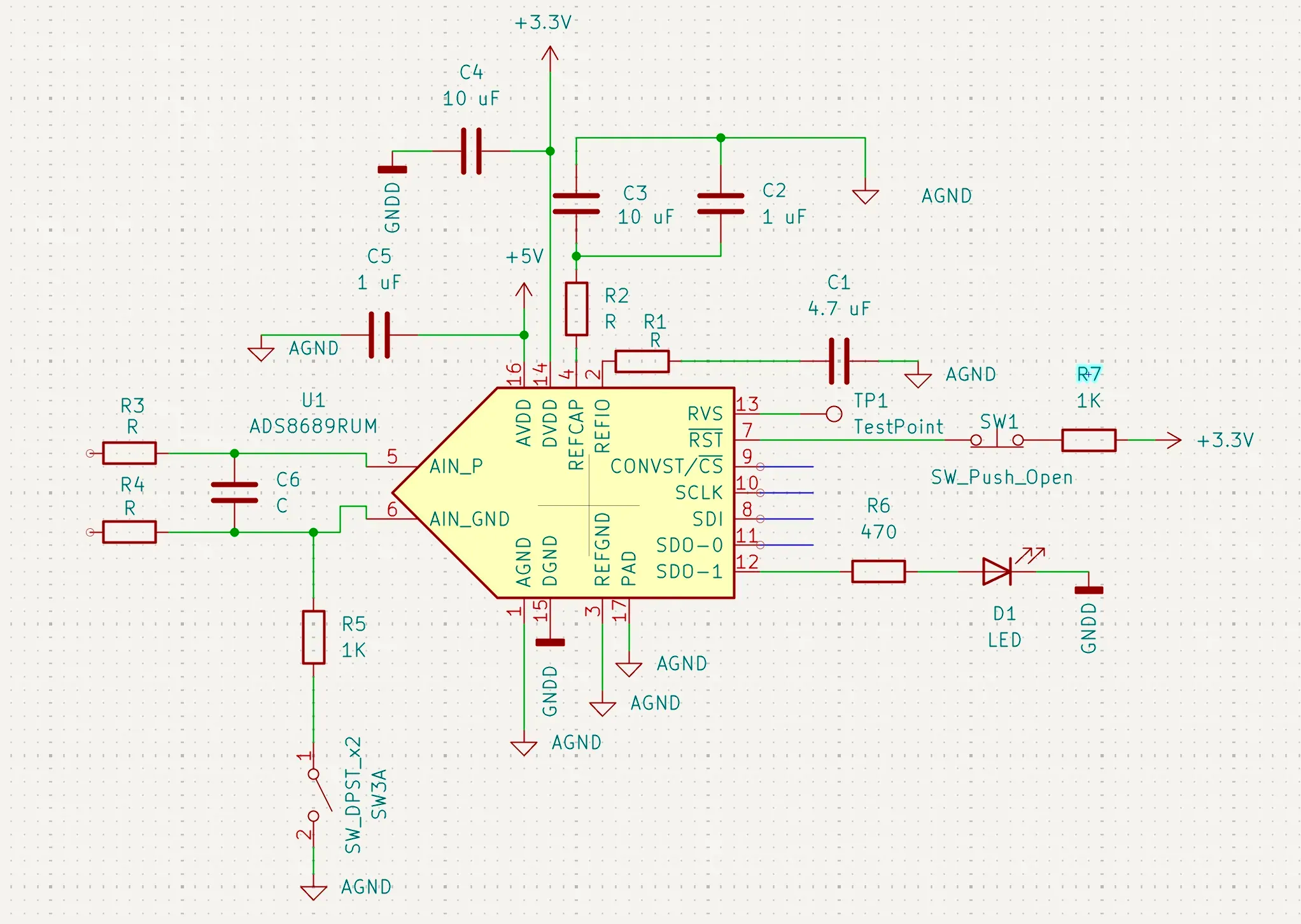
I am a new mechanical engineer, making an attempt at some basic PCB design. I am trying to use the ADS8689W to make a custom ADC board. I was hoping to get a schematic check to make sure I haven't made any goofy mistakes.

I was also hoping I could get some clarification / guidance on the implementation of Resistors R1, R2, R3, and R4. I know they need to be here but I honestly am not sure what their purpose is or how to calculate the appropriate resistance for them.  Any help would be greatly appreciated, thank you in advance for your help!

  • Hi Braden,

    Welcome to our e2e forum!  Pins 1 and 15 should be tied together - you can use the same net name or short them together with a zero ohm resistor.  Personally, I would add a small cap (100pF or so) between SW1 and pin 7 to minimize switch bounce.  R1 and R2 are not an absolute need, they represent ESR which you would need to review in the datasheet for the capacitor(s) - please review the bullet points in section 8.4.1.  For R3 and R4, you could start off with zero ohms and adjust later once you have the rest of your circuitry resolved.  Feel free to review the ADS8681WEVM-PDK schematic as well.

  • Hi Tom,

    Thank you for the reply and all of the helpful information! I will be sure to make the changes that you mentioned and check out the resources as well.