This thread has been locked.

If you have a related question, please click the "Ask a related question" button in the top right corner. The newly created question will be automatically linked to this question.

ADS8363 Single Ended Input - No Data

Other Parts Discussed in Thread: ADS8363, ADS8361, ADS8363EVM

Hi Folks -

I'm trying to modify a design here that was using an ADS8361 EVM at 500Ksps to use instead an ADS8363 EVM at 1Msps.  We have a single-ended input from 0-5V connected to A0+ through a simple op-amp buffer and have left A0- disconnected.  This worked perfectly fine for the ADS8361 EVM but when I swap in the ADS8363 EVM (which has, as far as I can tell, a compatible pin-out), I get nothing but a value of zero for the conversion result.  Now - if I tie the A0- input to ground (instead of leaving it floating), I start getting correct conversion results - except that they are approximately half-scale.

I have a feeling that there is something fundamental and simple that I am missing here.  Any thoughts?

Thanks much,

Joe.

  • Hi Joe,

    What are you doing with the SDI, M0 and M1 pins of the ADS8363?  Have you looked through the ADS8361 compatibility mode section of the data sheet?  There are a few minor differences in the pin out and pin functions between these two parts.  The internal reference of the ADS8363 is powered down by default, that might be the cause of the behavior you are seeing.  Remove JP3 and apply a 2.5V reference source to TP4 to see if that gets you something other than zero.    Also, the RD input needs to be 1 SCLK side with the ADS8363, the ADS8361 did not have that restriction.

  • Thanks for the reply Tom.

    You are correct - using an external 2.5V reference allowed me to see some sample values other than zero (though not what I'm expecting - more of a large sawtooth).

    SDI, M0, and M1 are all tied low - Mode 1, Ch A only.

    I'm going through my McBSP settings again - not sure what would cause the converted values to come out as a sawtooth.

    Joe.

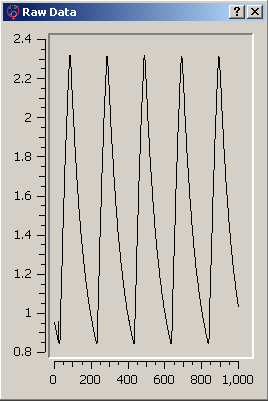
  • Here are a couple images to help describe what I am seeing.

    Image 1:

    This is what the converted signal should look like (except for the 0.5V offset that shouldn't be there).  I get this if I apply the input signal to A+ and connect the A- pin to ground through a cap.

    Now, if I remove the cap and leave the A- pin disconnected the way it works in our ADS8361 design, I get the following converted waveform:

    Image 2:

    Similar periodicity but wrong shape and levels.

    Does this indicate that I need to drive the input(s) differently between the ADS8361 and the ADS8363?  Or is there something else I am missing?

    Joe.

  • Hi Joe,

    The input stage of the ADS8361 versus the ADS8363 is a little different.  In both devices however, we normally recommend that a single ended input be coupled with placing the (-) input pin at the level of the reference (normally +2.5V).  That would allow you to swing the (+) input from 0-5V.  Tie the (-) input to the same 2.5V source that you used for the reference and let me know what you see. 

  • With the A- input tied to the 2.5V reference, I am now seeing the signal I am expecting (although it still has the 0.5V offset).

    By slowing things down a bit I determined that the input signal gets corrupted (the 0.5V offset) at the moment that I enable the clock and frame sync from the DSP.  Prior to that, I see a nice clean 0-3V pulse on my scope.  It almost looks like a power or ground problem but, just for comparison, I do not see this behavior when I swap the ADS8361 evm back in.

    Any other suggestions? 

    Thanks much,

    Joe.

  • Hi Joe,

    Can you grab a screen shot of that for me and let me know if any/and what changes you might have made to the input stage of the ADS8363EVM?