This thread has been locked.

If you have a related question, please click the "Ask a related question" button in the top right corner. The newly created question will be automatically linked to this question.

ADC3663: Quantized Output

Part Number: ADC3663


Tool/software:

Hello,

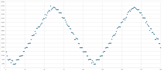
I am using an ADC3663 that is configured as follows and I am currently seeing a severely quantized 16-bit digital output when a continuous triangle wave is applied at the input

1. 2-wire mode
2. 16-bit
3. Default output bit mapping
4. No output scrambling
5. 20 MHz sampling
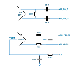
6. Differential analog input, differential SLVDS digital interfaces
7. No decimation (digital feature block bypassed)
8. Format A & B set to offset binary

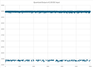
The quantizations in 16-bit space are roughly 4,096 counts apart (plus or minus 600 counts). See the capture below.

Both channels A and B look similar.

The test patterns look perfect w/ no sign of quantization (both the ramp and the fixed constant versions). The differential analog input at the ADC inputs also shows no sign of quantization.

What ADC misconfigurations might cause this quantization?

Update - ADC Clock & ADC Input Circuitry / Quantized Output of 2.0V DC Input

  • Hi Ryan,

    Can you detail your test setup for us and let us know what you are using for a sampling clock and analog input to digitize?

    Regards,

    Rob

  • Hi Rob,

    Thanks for your reply. I updated the original post to include a quick sketch of our ADC clock and analog input circuitry. I also wanted to show that even when we apply a DC analog input, we are still seeing some quantization noise on the higher order bits. Particularly on bits 14:12 which are most commonly "100" but occasionally (~1 in 20 samples) flip to "011" while the other bits remain constant. Again, none of this noise is present when the test pattern is enabled - neither with the ramp or the fixed constant test patterns.

    Appreciate the time spent on reviewing this issue with us.

    Ryan

  • Hi Ryan,

    Pleas answer my question on the setup details.

    Also, please forward the schematic regarding the amplifier circuit you posted. I need more details. Seem like the amp is imbalanced.

    A quick check here is, when no signal is applied, measure the DC value on both of the analog input pins with a DMM. Both should be around 0.95V DC.

    Regards,

    Rob