Other Parts Discussed in Thread: OPA325, ADC121C027
Tool/software:
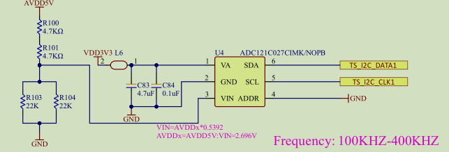
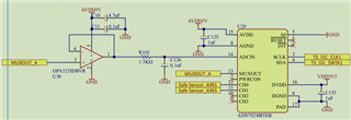
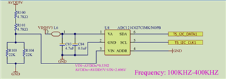
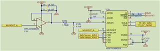
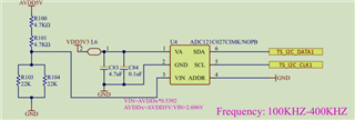
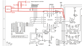
I am using I²C at 100kHz to read ADC data. There are two ADC chips on the I²C bus: one is ADS121C, and the other is ADS7924.
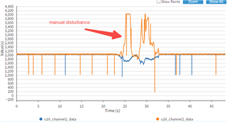
I am reading data from both ADCs in a loop running at 1kHz. The data from ADS121C is stable and within the expected range, even when there are minor fluctuations.
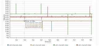
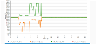
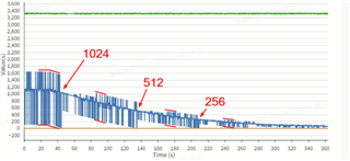
However, the data from ADS7924 shows glitches and abnormal jumps on all channels. For example, the normal value might be 2500, but it occasionally jumps by powers of two — like increasing by 2048 to 4548, decreasing by 2048 to 452, or jumping by ±1024, ±512, ±128, ±64, ±8, etc.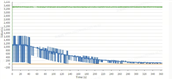
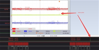
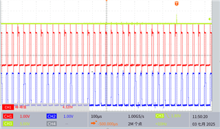
green data is 121C, blue data is 7924.
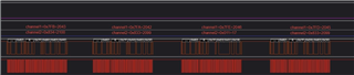
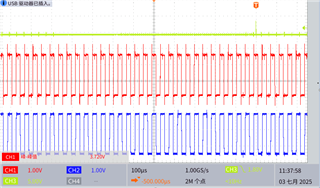
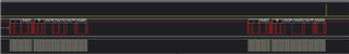
I have checked the I²C waveform on an oscilloscope and found no obvious issues. However, the data captured by a logic analyzer confirms that the raw values returned by the ADS7924 are incorrect during those jumps.
What could be the cause of this? Is there something I might be missing in the read process for ADS7924?
Thank you!


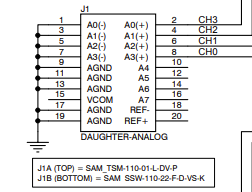
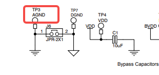 GND used TP3(AGND).