Other Parts Discussed in Thread: ADS127L18, ADS127L14, ADS127L11
Tool/software:
Hi, i'm currently working on a project involving the ADS1261 device. Currenty i'm in the testing phase, where i want to verify if i can read back the correct analog values using the mentioned device. My setup involves an improved howland current source (VCCS, sinusoidal current source with 1mA amplitude), which i drive with my ESP32. On my scope i could verify it outputs the correct frequency (10 kHz) sinusodial waveform. For testing the ADC i set up an environment, where i drive the sinusodial current through a 1.1 kOhm resistor, and try to measure the voltage drop accross it using the ADS1261.
Before the ADC there is a signal conditioning circuit consisting of buffer amplifiers (AD8244) and high-pass RC filters (33nF, 10kOhm) and the output of these is connected to the ADC.
I set up the ADS1261 to use the internal 2.5V reference, GAIN=1, sampling rate 40 kSPS and set the INPMUX register to 0x23 to measure the voltage drop between these channels.
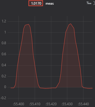
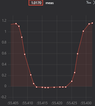
For the cases when i set the VCCS frequency to 1 kHz i can clearly reconstruct the signal, it looks what i intended, this is shown on the following figures.
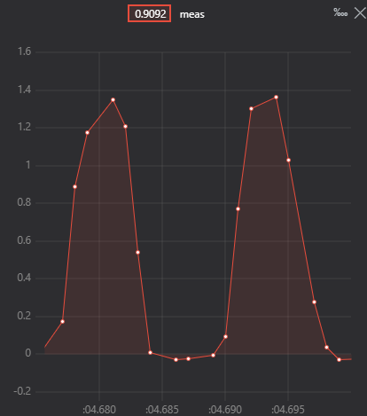
My problem is that when i raise VCCS frequency the sampled signal gets distorted. I understaned, that by raising the frequency the sampling should contain more noise, this seems trivial, but i feel like not the amount i experience. When i raise the frequency to 2 kHz the sampled signal looks like this (not awful, but clearly visible distortion):
And finally what is my main problem is that i would like to sample a 10 kHz signal using the device, and in this case, the measured values looks just like noise, not even close to what i would imagine. I don't really understand what could be the problem, since im far beyond the Nyqusit limit (f_samp > 2 * f_sig), and currently i have no idea what am i doing wrong, such that the measurement results are complete non sense. Can you please help me, what could i do in this case, or what can i do to avoid this behavior? (In case of each signal, i attached, i have verified with my scope, and im sure they are close to the right waveform.)
The project of mine is available here: EITHardware/ADS1261.hpp at main · balazs42/EITHardware
Thanks in advance!
-Balazs