This thread has been locked.

If you have a related question, please click the "Ask a related question" button in the top right corner. The newly created question will be automatically linked to this question.

DAC8750: Regarding unused pin

Part Number: DAC8750
Other Parts Discussed in Thread: DAC8760

Tool/software:

Dera support

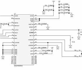
We are designing a circuit for the DAC8750.
We have a question regarding unused pins.
If we are not using the functions of the ISET-R pin, HART-IN pin, and CAP1 & CAP pin, is it okay to leave them unconnected?
Also, if we are using the internal RSET, is it okay to leave the Control Register DB13 (REXT) setting at its default?

Thank you
Best regards

YUSUKE
 
  • Yusuke-san,


    The CAP1 and CAP2 pins can be left unconnected. Capacitance at these pins are used for filtering the output of the device and you can see the change in settling time when these capacitances are added in Figures 8-4 and 8-6 in the data sheet.

    ISET-R can also be left unconnected if the internal set resistor is used. If you are using the internal resistor, you would leave DB13 of the control register as 0 as you mentioned in your last post.

    If HART is not used, I would connect the HART-IN pin to ground through a 22nF capacitor.

    Let me know if you have any other questions.


    Joseph Wu

  • Hi Joseph-san,

    Thank you for your reply.
    Will there be any effect on operation if I do not connect the 22nF capacitor to the HART-IN pin?

    Best regards

  • Yusuke-san,

    I would guess that there would be no problem. However, because the node is a little higher impedance (~35kΩ), I would generally like to make sure there is a low impedance, high frequency path to ground. I would be concerned that EMI might create some noise if this node is left floating and that would cause some output change. 

    For the current/voltage version of this device (DAC8760), we did an EMC tested version of the EVM. You can find the EVM information here:

    https://www.ti.com/lit/ug/sbau229/sbau229.pdf

    For all of the pins that you mentioned, there are connections to each one:

    However, I think the HART-IN pin has the highest input impedance, and would like be most susceptible to EMI. Because of this, I think using the 220nF capacitance at that node is more important than the other nodes.

    Joseph Wu

  • Also, there is a TI design that describes this EVM with a little more detail. You can find the design folder here:

    https://www.ti.com/tool/TIPD153

    And the design guide here:

    https://www.ti.com/lit/pdf/tidu011

    Joseph Wu

  • Joseph-san,

    We are planning to perform EMI testing and will follow your advice to connect a 0.22nF capacitor to the HART-IN pin.
    I can proceed with the circuit design thanks to your advice.

    Thank you.

    Best regards

    YUSUKE