This thread has been locked.

If you have a related question, please click the "Ask a related question" button in the top right corner. The newly created question will be automatically linked to this question.

ADS8588S: Looking for guidance on running this ADC in serial mode

Part Number: ADS8588S

Tool/software:

I have been running the ADS8588 dev kit in parallel mode with good results for a few months. This week we decided to convert to a serial interface, and now I am scrambling to get it working as it should.

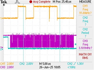
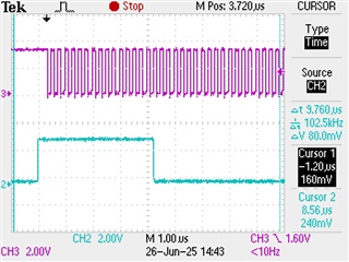
I set the jumper J3 on the board to select serial mode. The two conversion start pins are tied together. My code issues a reset to the converter for 100ms, and then I have a test program issue a single conversion request, which I can see answered by the BUSY line's pulsing high and then low (this is the blue trace in the images). That low transition is the signal that starts clocking the data in from port A, using a 3MHz clock, plenty slow enough according to the data sheet. You can almost see each packet of sixteen pulses in the purple traces, one burst for each of the eight channels.

The problem is shown in the orange trace. All of my inputs are grounded, and yet the readings are all over the place. Sometimes I get all zeros as I should, or nearly so within the expected margin of error. But other channels may have all their bits high, as if I have applied the full voltage rail to them. I can find no pattern to the behavior. Can someone offer a suggestion based on experience as to what I may be overlooking when moving to the serial interface?

One additional note is that we will not have access to a SPI bus, so I have been clocking the RD line from a PWM generated output on my micro and simply reading whatever is presented on the ADC's data port. Is there a known issue with bit banging the port in serial mode? I appreciate any inputs. 

Thanks

Here: grounded channels 4,5,6 and 8 show all high inputs -

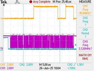
Here: now all good except channels 5 and 6...

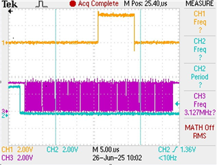
Now half the channels are good, and half in error:

  • Hi Vince,

    Welcome to our e2e forum!  Did you use the GUI that comes with the ADS8588SEVM-PDK and verify that serial mode is working correctly?  Do you still have the PHI connected to the EVM while you are trying to run the part in serial mode with your own hardware?

  • Thanks, Tom. I only used the PHI initially, before we went very far with development. The EVK is wired up to a micro. In the absence of any obvious issue being pointed out, I may have to dig that back up and start from scratch. (Can you think of anything else that could cause these symptoms? This actually is the second board we received, brand new; the first board is part of a jungle of wire, running in parallel mode in another department. I had no issues with it.)

  • Hi Vince,

    If you go through the datasheet and to some extent the EVM Users Guide, there are several parallel data lines that need to be terminated.  Without the PHI you may need to short those pins on the EVM to ground.  

  • You know, I saw that the other day while working on a PCB layout and wondered how that could affect the DVK. I concluded it shouldn't much matter, but now I'm not so sure. I think I can ground those points easily enough. Thank you for your suggestion.

  • When you use the GUI, the PHI controller pulls those pins to ground.

  • I am grateful for your help. I am going to experiment with the PHI board the rest of today and tomorrow. I will be sure to let you know the result. If I can get good results with that, I will at least have some confidence modifying the board afterward.

  • Tom, that didn't take long at all. I got the PHI out and set it up for serial communication. I would like to run the result by you, because I may just be confusing myself. The GUI shows a fantastic reading for grounded inputs. See the picture - I'm not sure how good the resolution is for the screenshot, but the numbers are in the several microvolts region. Just noise. The scope, though, is showing pretty much what I saw on my own setup. The blue trace here is the data for the first four channels, clocked by the purple trace at 4MHz. Even though the GUI shows channel 1 rock solid in the noise floor, I often see all 1's coming out of the Data A port. It fluctuates, as before, between reporting zero and pegged to the rail. I'm not sure how the GUI is calculating the (correct) values, given the actual signals I am getting out of the ADC. As before, thanks for the valuable insights.

  • Never saw a purple o'scope channel before...  Where are you probing on the EVM with CH2?

  • Scope channel 2 (blue) is EVK test point 7, which is labelled DOUTA. That high signal spans exactly 16 clocks, like I am measuring the negative full input instead of ground (you can thank Tektronix's screen capture utility for the hideous purple rendering). It appears that the GUI program is putting out the first four channels on that port. Analog input 1 is all 1's, and the rest are all 0's. You can see results from input 2 and part of 3 in the picture, but the pattern changes sample to sample. Sometimes input 1 is all zeros. I don't even trust that the zeros are correct, either, since it is almost always the case that I get some fluctuation in the lower bits, plus about half of the data points should be in the negative noise region and indicated by a high MSB. I am sure I am making some bone head mistake here, but I am just not seeing it at all. If I had to replicate what the GUI is reporting with this data stream, I couldn't do it.

  • Hi Vince,

    Thank you for the added detail.  The ADS8588S has a binary 2's complement output, so you are actually seeing the correct data (my bone head afterthought).  Full scale negative would give you 0x8000, FS positive would be 0x7FFF.  When you ground the inputs 0x0000 and 0xFFFF are one code away from each oher.

  • Tom, just as your email came through, I had finished a test in which I captured a single sample in the GUI and the scope, calculated what should have been the counts, and compared. I suddenly realized that the 2's complement form of the answer would indeed produce 0xfffe (or thereabout, depending on the amount of error in those last bits). Thank you for your insights, and I apologize for dragging out what I should have known late yesterday. You have been most helpful and kind.