Other Parts Discussed in Thread: AMC3306M25, AMC3306M05
Tool/software:
New to using Sigma Delta Modulators, need sanity check.
Have some basic questions, questions I guess, are related to both the AMC3306 and the F28379D MCU.
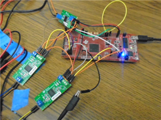
Using AMC3306EVM (eval board) along with a LaunchXL_F28379D (C2000 MCU); MCU is providing the Sigma Delta Filters for the 3306 Sigma Delta Modulators. Have a question regarding the input data range vs output of Sigma Delta Filters (MCU_output)
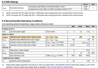
AMC3306EVM comes with AMC3306M25 Sigma Delta Modulators installed so, signal input range is ± 250 mV.
I replaced the AMC3306M25 with AMC3306M05 (± 50 mV; input signal range)
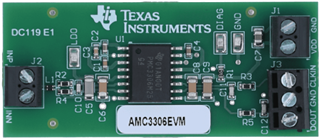
3306EVM
Using a 3 channel arbitrary waveform generator to input sinusoidal signal into INP and INN ports of J2 on 3306EVM.
Below is part of simulink model using LaunchXL_F28379D as target
- Using F28379D for Sigma Delta Filters
- Using F28379D ePWM for Sigma Delta Clk
- clk to Sigma Delta Modulator (AMC3306EVM)
- clk to Sigma Delta Filters (F28379D)
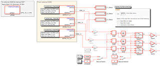
FIGURE 1 - Simulink Model deployed to F28379D
To see full (rail to rail) waveform out of Sigma Delta Filters:
- Set Input (signal source) DC Offset to +27 mV
- Set input (signal source) Amplitude to approx 63 mV pk to pk (approx ± 31 mV ref +27mV dc offset)
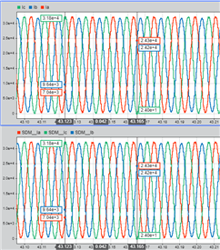
- With these settings below is image of what I see on output of Sigma Delta Outputs
- apologize for the small hard to see image
- Top set of waveforms are being measured towards the end of the model shown in FIGURE 1.
- Signal is centered about a count of 16384
- high side pk is very close to 32768
- low side pk is very close to 0
- Bottom set of waveforms is directly out of MCU SD Filters
- Identical to the waveforms described above.
- Top set of waveforms are being measured towards the end of the model shown in FIGURE 1.
- apologize for the small hard to see image
Questions / comments:
Am using Sin3 filter setting on the MCU SD Filters (Filter has option for 16bit or 32 bit representation); 3306M05 datasheet says 16 bits of resolution can be achieved. (2^16 = 65635; 2^15 = 32768)
- Did not see difference in SD Filter output range related to filter resolution option; 16 or 32 bit
From what I am seeing.. max signal I can get out of SD Filter is 0 to 32768) why?
Should it be 0 to 65635 or is msb supposed to be an indicator of positive / negative excursion
My signal into the SD modulator is approx 60 mV pk pk.. with a 27 mV dc offset; This is a signal of ± 30 mV pk, right? Should it not be at least ± 50 mV?
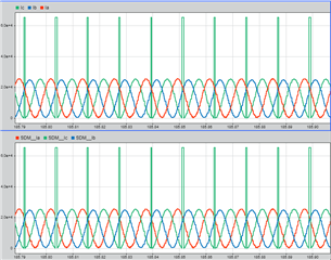
Lowering my input signal amplitude to approx 50 mV pk to pk (± 25 mV) then lowering DC offset to approx 22 mV I get the following waveforms:
Again sorry for the hard to see image: (again top and bottom plots are practically identical
- Bottom set of waveforms are being measured at output of SD Filter blocks shown FIGURE 1.
- since DC offset was lowered so was the center point of waveforms
- low side pk... green waveform is just starting to touch a zero count; then looks like it wraps up a max count of 65635.
What am I missing?
Is it how I am driving Modulator?
Are these output waveforms correct?
Am I using the MCU Filters correctly?