This thread has been locked.

If you have a related question, please click the "Ask a related question" button in the top right corner. The newly created question will be automatically linked to this question.

DAC8775EVM: Minimum parts required

Part Number: DAC8775EVM
Other Parts Discussed in Thread: DAC8775,

Tool/software:

Using the DAC8775 for a specific project and would like to know how to limit the number of components needed to support the DAC8775.

If JP1 and JP2 are both set to 2-3 ie using the external power AVDD and AVSS, do I need any of the supporting components between LN_A to JP1-1 

ie L1, D1, C1, FB1, C5, R1, C9

between LN_B to JP2-1 

ie L1, D3, FB2, C6, R2, C100, C6

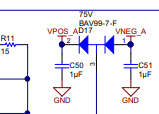
Also if it is a fixed circuit with fixed AVDD and AVSS is there any real need for D5 and D6?

I have asked for one channel, but assume that the answer reads across to the other 3 channels?

  • James,


    If you plan on using external supplies, you could the circuitry at VPOS_IN_x and VNEG_INx, and then leave LP_x and LN_x unconnected. Then you could connect decoupling capacitors to the tied nodes of VPOS_IN_x, AVDD and PVDD. VNEG_IN_x would need a decoupling capacitor if used as a negative external supply. The circuitry on the EVM is used as part of the buck-boost converter for the DAC8775.

    You can just follow Figure 137 in the datasheet as a guide:

    From your list, I think you'd only need C5 and C6. Just make sure VPOS_IN_x is tied to PVDD/AVDD.

    Let me know if you have any other questions.


    Joseph Wu

  • Joseph

    Thanks for your reply.

    I currently have VNEG_IN_x connected to -15v

    and VPOS_IN_x connected to +15v

    Both decoupled independently to GND 1uF   (I see that I might get away with 0.1uF)

    Also PVSS_x all connected to Gnd

    See attached, I might have over done it with the capacitors!!!

  • James,


    I think that's ok. If this is going into an industrial environment, I'd put in the output protection that is shown in the EVM with the extra protection diodes (TVS and Schottkys) that protect the device from transient voltages like ESD.

    Here's the picture from the EVM:

    Joseph Wu

  • James, 

    If you don't already have one, I would suggest getting a DAC8775EVM just to play with this circuit. The modifications to run this EVM on an external supply are rather minimal, and you should be able to test and run anything you want with it.

    https://www.ti.com/tool/DAC8775EVM

    Joseph Wu

  • Joseph

    Thanks so much.  

    I do have the DAC8775EVM and been working with it for sometime.

    I have it setup as described and have written extensive library for controlling it using a micro.

    The reason for contacting TI was to ensure that the additional components on the EVM did not interact with other jumper options, which you have confirmed.

    You comment on the output protections.  The output goes to a comparator circuit that has 3kΩ before it sees the outside world.

    From your diagram, are you suggesting  D19 would be appropriate and thus protect the output?

    Given that it is a fixed voltage to VPOS_x and VNEG_x  and can't be a variable as it can be on the EVM board, I am not sure that I would need the over-voltage protection D17 C50 C51 and D? shown below.  Welcome your thoughts

  • James,


    The 3kΩ of resistance is probably all that's needed to protect the output. It limits the current that goes to the device outputs. Normally we have the diodes there to shunt away an transient overvoltage that might hit the outputs, such as an ESD event.


    Joseph Wu