This thread has been locked.

If you have a related question, please click the "Ask a related question" button in the top right corner. The newly created question will be automatically linked to this question.

ADS1259-Q1: If this ADC is capable of converting fully differential and true bio-polar signal (Schematic attached)

Other Parts Discussed in Thread: ADS1259-Q1, ADS1259, THP210

Tool/software:

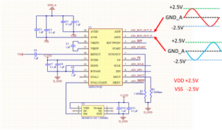
As shown in the ADC schematic, CH1_BUF_OUT_P and CH1_BUF_OUT_N are fully differential and true bipolar signals generated by a preceding fully differential amplifier (THP210DR, not shown here).

Our intention is to leverage the high common-mode rejection ratio (CMRR) provided by the fully differential ADC.

Given this design approach, I would like to confirm whether the ADS1259-Q1 is suitable for achieving our objectives in terms of  taking fully differential and true bipolar input.

Thank you very much.

  • Hi Xinyu Wu,

    The ADS1259 can technically support +/-2.5V inputs using a +/-2.5 bipolar analog supply. I assume the reference point in your waveform drawing should be D_GND, not GND_A, because your signals are negative with respect to that net. Your analog ground in this case should be VSS.

    You however might want to reduce the output of the THP210 to something like +/-2.4V to give yourself some headroom and avoid saturating the inputs

    -Bryan

  • Hi Bryan,

    Thanks for the reply. I didn't get the part that "the reference point in the waveform should be D_GND". On the board, we do provide both positive and negative analog power rail (VDD(+) and VSS(-)) paired with GND_A (analog ground). The digital power supply marked as 3.3VD paired with GND_D. The signals we try to digitize are also analog bipolar and that's why I put GND_A as the reference point. Does this make sense?

    Thank you for recommendation and I will adjust the THP210 output to provide some headroom.

  • Hi Xinyu Wu,

    I assumed you had a single ground for both analog and digital that was labeled D_GND, which is what we typically recommend. But if you have a separate analog ground (GND_A) then I agree your drawing makes sense

    -Bryan