This thread has been locked.

If you have a related question, please click the "Ask a related question" button in the top right corner. The newly created question will be automatically linked to this question.

ADS8355: Do I need ADC driver amplifier if sensing low side current using INA296 or OPA2863A?

Part Number: ADS8355
Other Parts Discussed in Thread: OPA2863, INA296B, , ADS7853

Tool/software:

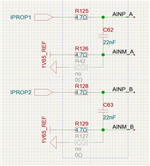
Hi, we would like to use ADS8355 to sample two legs of low side current of a H bridge, The current sensing are using INA296B (we will also evaluate using OPA2863 to build a low side current sense circuit) and a shunt resistor, can we connect the output pins of INA296 directly to ADS8355 via a RC network without any driver amplifier?

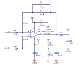
For OPA2963, the schematic is like TIDA-060019A

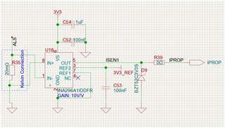
and for INA296, the schematic is like follows,

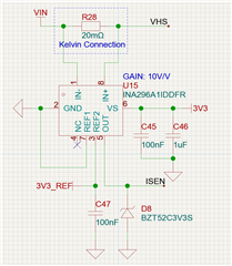
The question is that can we directly connect ISEN or AVout to ADS8355 via an RC without any driver amplifier to minimize BOM.

BTW, what is the criterion of adding ADC driver amplifier? the output impedance?

  • Hello Benyuan Liu,

    For the ADS8355 at full sampling speed (1MSPS), yes, you do need an ADC driver for the INA296 current sense circuit. The low side current measurement with the OPA2863, could be able to drive the ADC directly without an additional driver, if the RC is adjusted accordingly. 

    Do you plan to use the ADS9355 at 1MSPS? if the sampling speed is slowed down and/or some error is permitted the INA296 would be able to directly drive the ADC with an RC. 

    For H-Bridge and current shunt measurements, we have these documents that can help go through the process of the component selection with SAR ADCs:

    A Basic Guide to Bridge Measurements

    Circuit for Driving a Switched-Capacitor SAR ADC With an Instrumentation Amplifier

    Circuit for Driving a Switched-Capacitor SAR ADC With a Buffered Instrumentation Amplifier

    High-Side Current Shunt Monitor Circuit to 3-V Single-Ended ADC

    Low-side current shunt monitor circuit to 3-V single-ended ADC

    And for more information on ADC driver selection our Precision Labs Series and Amplifiers and Bits: An Introduction to Selecting Amplifiers for Data Converters are great resources for the type of specifications to look into when selecting and ADC and ADC driver. 

    Best regards, 

    Yolanda

  • Thank you, I plan to use INA296 + ADS8355 for dual leg (a H bridge) current sensing. The speed are required to run at 1MSPS and possibly more higher, the resolution can be lower to minimal 12bits. We also consider ADS7853 for a low cost option.

    Why INA296 cannot be connect directly to ADS8355 when the sampling frequency is 1MSPS? I calculate the RC filter to be 4.7Ohm and 22nF, and sampled at 1MSPS, is it OK to do so?

    And this board is area limited, could you please recommended some small OpAmp for use as a buffer?

  • Hello Benyuan Liu,

    Ideally yes, but the INAs don't typically have the bandwidth to drive precision ADC, which is why when using an INA it is recommended to incorporate an additional stage that would be able to drive the ADC or to slow sampling rate down to a point where the INA would be able to drive the input. 

    To drive the ADC the source should be able to drive the switched capacitor load of the ADC and settle within 1/2 of an LSB within the acquisition time (for the ADS8355 this is 350ns; please also note that it should not just be settled by the 350ns, but a bit before to allow accurate measurement of the settled signal). The RC filter at the input of the ADC is also incorporated as a charge kick back filter to help allow the ADC's  switched capacitor to charge and settle within the acquisition time (as well as help with aliasing). 


    Typically the bandwidth needed to drive an ADC is at least 10x the sampling frequency for lower resolution ADCs, but it could be even higher depending on acquisition time, resolution, and range. With the INA296 having only a 1.1MHz bandwidth, it would not be able to drive the ADS8355 directly without slowing the sampling down or aiming for lower resolution measurements. 

    Other things to consider beyond the bandwidth of the INA is the driving capability. It should not just have the bandwidth and slew rate capability to settle the signal, but also charge the RC filter + the switched capacitor load of the ADC. I couldn't find current output for the INA296 in the datasheet, but it does have a maximum capacitive load of 1nF, making your suggested RC too large to drive. Typically we recommend using 10-20x the sample and hold capacitor of the ADC as the capacitor value of the input RC (for the ADS8355, this is 40pF) so 400-800pF would be drivable, but the INA would probably take >1us for the signal to settle. Lowering the sample speed <500kHz might make it a possible option though. 

    We have this TechNotes document that goes over Driving a SAR ADC input without a Driver Amplifier and could be helpful if you are interested in this route. 

    I would also recommend looking into our Analog Engineer's Calculator, which is also helpful at designing these circuits for not just data converters but for amplifiers and more. TI Precision Labs also have a lot of information: 

    For drivers I would recommend the OPA320 which is also ~3mmx3mm or the OPA836 with ~3mmx3mm and even 2mmx2mm packages. 

    If the 1MSPS is required, with at least 12 bit and size is priority, we also have the ADS7056. It is a 14-bit, 2MSPS, Single-Ended SAR ADC with a 1.5mmx1.5mm package. or its 12-bit, 3MSPS version in the same package, ADS7046

    We also have some ADCs with integrated drivers that allow for more direct inputs, like the ADS8681W, this one is a 16-bit, 1MSPS, SAR ADC with integrated PGA and a package of 4mmx4mm.

    Best regards, 

    Yolanda