


Other Parts Discussed in Thread: INA159, INA826
Tool/software:
Hello TI Support Team.
we use the TI product ADS1248 in one of our products for voltage, current and temperature measurements. Lastly we encountered a huge amount of errorneous devices, where the measured voltage was way off the expected result. We did some research, which I will share with you and we need a statement from TI to our results.
Measurement deviation
When measuring a voltage on any of the inputs of different ADCs, we see deviations that shouldn't be possible when looking at the datasheet. The datasheet mentions a gain error of max -+0.02 %, which is 2 mV for a 10 V input voltage. We see a deviation of 16 mV and more for an input voltage of 9.5 V. It depends on the ADC and some ADCs are measuring fine, others have that unexpainable big error.
Input Stage before the ADC
We use the same input stage for each channel to the ADC as TI does in some of the reference designs using a INA826 and a INA159. Please see the included picture for the schematic. As reference we use an external precision reference voltage source with a reference voltage of 2.5 V and an max error of +-0.04%.

I did a measurement series over more than 15 devices to verify, that the input stage is correct. Here is one of the stages as example. The other ones follow the same principle and the results are all in the expected range.
Input INA826: 4.2491 V
Output INA826/Input INA159: 4.2491 V
Output INA159/Input ADC: 3.3492 V
Reference Voltage ADC: 2.4994 V
With this input, the ADC measures a voltage (reduced to 16 bit) of 4.245 V. Thats one of the better ADCs.
ADC, result calculation and more
During our investigation we produced around 70 boards with ADCs taken from different reels with different LOT numbers, just to see, if we have a LOT dependent error. To check, if the computation in our software is correct, I took the read raw value and processed it with our algorithm and another different one I wrote during the tests. Both delivered the same results.
The fascinating part comes now. I also read the FSC register. Our assumption was that each ADC has its own set of GAIN calibration values for the FSC registers. The results for differend LOT numbers were interesting...
We tested with two gain settings of 1 and 2 respective. We did a readout of the FSC register after the gain was changed.
All ADCs with a datecode of 2337 from two different LOTs (3723526ML3 and 3723539ML3) have the same readings for the FSC registers. A gain of 1 gave us a FSC value of 0x400E00, a gain of 2 had a FSC value of 0x400D80. Those values are the same for ALL of the ADCs from the LOTs mentioned above.
To be sure that we didn't made an error, we tested with another LOT with a different datecode which was known as "good" reel. Devices that had an ADC from that reel did never exceed our error limit. The reading of the FSC value were different for each single ADC, as we expected.
| GAIN 1 | GAIN 2 |
| -------- | -------- |
| 0x4007c0 | 0x400b00 |
| 0x400bc0 | 0x400840 |
| 0x4004c0 | 0x400180 |
| 0x401980 | 0x400fc0 |
| 0x401c40 | 0x401700 |
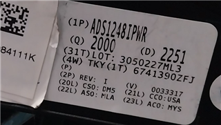
Here are the labels of both the reel with ADCs where all have the same gain correction value (datecode 2337) and the reel with the ADCs where each has a separate gain correction (datecode 2251).
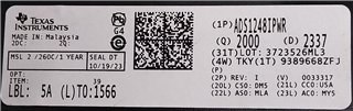
Unfortunately I don't have the whole label from the "good" reel at hand, production marked them with an own label as "special". If necessary, we can try to get the other label off and take a new image.
What we now need is an explanation from TI why the ADCs with the given LOT numbers have all the same gain correction values. We checked for a PCN for that device, but nothing was found (also one of our distributors checked for PCNs). We have a lot of ADCs that don't work as promised in the datasheet and we spend a lot of time and effort in researching this issue.
Best Regards
Frank Erdrich
