Tool/software:
Hi. We are having trouble making the 7038 read from any of the input channels except the first one at RECENT_CH0_LSB 0xA0.
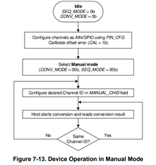
Included below is a brief version of our bootup code to configure the 7038 in manual mode with eight analog inputs.
u8 register_byte = 0;
/* Enable CRC Disabled until initial testing is done */
/* register_byte |= ADS_7038_REG_CFG_CRCEN; */
/* Enable Statistical Model Disabled */
/* register_byte |= ADS_7038_REG_CFG_STATS; */
/* Enable Digital Window Comparitor Disabled */
/* register_byte |= ADS_7038_REG_CFG_WINDW; */
/* Leave CONV_MODE bits 5,6 on zero to select manual mode */
/* Enable ADC Calibration Disabled */
/* register_byte |= ADS_7038_REG_CFG_CALIB; */
/* Set all channels to analog input */
register_byte |= ADS_7038_REG_CFG_ANALG;
/* Reset the slave using the configuration register reset bit. */
register_byte |= ADS_7038_REG_CFG_RESET;
ADS_7038_Reg_Write(InstancePtr, ADS_7038_REG_CFG_ADDRS, register_byte);
/* Set opmode configuration register to low speed oscillator internal timing. */
register_byte = ADS_7038_REG_OPM_LOWSP | ADS_7038_CLK_DIV_09;
ADS_7038_Reg_Write(InstancePtr, ADS_7038_OFFSET_OPMODE_CFG, register_byte);
/* Set all options to zero in the sequence configuration register to select manual mode */
ADS_7038_Reg_Write(InstancePtr, ADS_7038_OFFSET_SEQUENCE_CFG, 0);
/* Select all channels for reading (Tried with and without for manual mode no effect). */
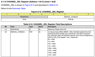
ADS_7038_Reg_Write(InstancePtr, ADS_7038_OFFSET_CHAN_SELECT, 0xFF);
/* Read back the channel select register to confirm. */
register_byte = 0;
ADS_7038_Reg_Read(InstancePtr, ADS_7038_OFFSET_CHAN_SELECT, ®ister_byte) > 0);
/* Returns 0x00 No channels selected. */
READ RAW ADC
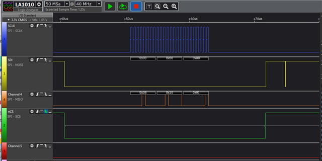
Below is the section of code which reads the ADC from the 7038,
and it works great but only for the first channel zero.
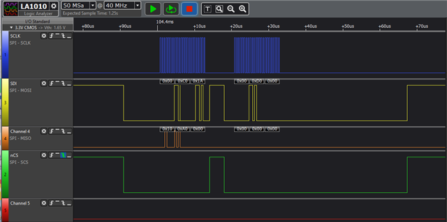
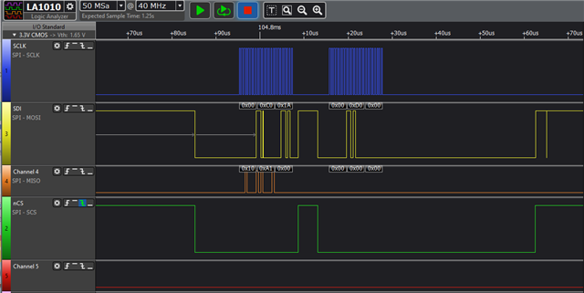
/* Select the channel */
ADS_7038_Reg_Write(InstancePtr, ADS_7038_OFFSET_CHANNEL_SELECT, (u8)index_channel);
/* Read back to confirm. This always returns zero even if second channel 1 selected above */
ADS_7038_Reg_Read(InstancePtr, ADS_7038_OFFSET_CHANNEL_SELECT, &chan_confirm);
/* Read the LSB and MSB from the 7038 and combine to get the raw ADC value */
u8 register_lsb = 0;
u8 register_msb = 0;
s32 status_lsb = ADS_7038_Reg_Read(InstancePtr, offset_channel, ®ister_lsb);
s32 status_msb = ADS_7038_Reg_Read(InstancePtr, offset_channel + 1, ®ister_msb);
register_msb = (register_msb >> 4) & 0x0F;
analog_reading = (u32)register_lsb + ((u32)register_msb << 8);
Voltage readings are correct but only if a test voltage is applied to first pin channel zero.
If any other channel is selected it still only reads the value from channel zero.
SOFTWARE LOG OUTPUT
Read ADC channel 1 select write = 0x00000001.
Read ADC channel 1 select confm = 0x00000000.
Read ADC channel index 1 block = 0x000000A0.
Read ADC channel index 1 offst = 0x000000A2.
Read ADC raw = 0x002991A8 voltage = 0.000
Any advice on how to select the other analog input channels 1-7 in manual mode much appreciated.
Everett Sellner