This thread has been locked.

If you have a related question, please click the "Ask a related question" button in the top right corner. The newly created question will be automatically linked to this question.

ADS124S08EVM: Request for EVM Design Files and Clarification on ADS124S08 Usage

Part Number: ADS124S08EVM
Other Parts Discussed in Thread: ADS124S08

Tool/software:

Hi Team,

I’m planning to use the ADS124S08 ADC in our upcoming application. Could you please share the EVM design files for this device? Having access to the reference design would greatly help in completing our circuit development efficiently.

Additionally, I have a few technical queries and would appreciate your clarification:

  1. Is it possible to use an external excitation supply for the RTDs?

  2. I have 6 RTDs and 2 thermocouples in my system. I’m planning to interface them using a single ADS124S08 chip with an external analog multiplexer. Is this configuration acceptable?

  3. Can the AVSS pin of the chip be connected to a negative voltage supply?
    This is required because my input signal range is –125 mV to 250 mV.

Looking forward to your support.

Thanks & Regards,
Manikandan V

  • Hi Manikandan Velayudham,

    I can provide you with the EVM gerber files if you would like, but we don't share the design files for our EVMs. And of course we provide the schematic and the BOM in the EVM user's guide. Let me know if you would like the gerber files

    Regarding your other questions:

    Is it possible to use an external excitation supply for the RTDs?

    Yes, why wouldn't this be possible? Of course the ADC already has integrated current sources specifically for RTD biasing, so you don't need external components. 

    I have 6 RTDs and 2 thermocouples in my system. I’m planning to interface them using a single ADS124S08 chip with an external analog multiplexer. Is this configuration acceptable?

    Yes, basically any configuration is possible with external multiplexers

    Can the AVSS pin of the chip be connected to a negative voltage supply?

    Yes, refer to the Recommended Operating Conditions table in the ADC datasheet for more information about the possible supply voltages 

    -Bryan

  • Hi Bryan,

    Could you please share the Gerber files for our reference to assist with layout planning?

    I will complete the design and share it with you for review as soon as possible. Kindly keep the ticket on hold until then.

    Thank you,
    Manikandan V

  • Hi Manikandan Velayudham,

    Yes, I will need some time to prepare the files and provide them to you, please give me until the end of next week to do so

    Thanks for your patience

    -Bryan

  • Hi Manikandan Velayudham,

    I have prepared the files and have submitted the request for them to be added to the EVM tool folder. I'd expect this to be completed by the end of the week, but I'll let you know

    -Bryan

  • Hi Bryan,

    Thank you for your efforts in getting the EVM Gerber files ready.

    I’ve completed the ADC interface for 4 & 3-wire RTDs and one thermocouple. Please find the attached schematic PDF for your review and feedback.

    I also have a couple of questions regarding the SPI interface:

    1. Are the START/SYNC and DRDY pins necessary for SPI communication? Could you clarify their role and whether they are required in a typical setup?

    2. I have another slave device sharing the same SPI bus. The datasheet recommends placing 47 Ω resistors on the SPI lines. Will these resistors affect communication with the other slave device? Your insights would be helpful.

    Thanks again for your support.

    Best regards,
    Manikandan V

    RTD SCH.pdf

  • Hi Manikandan Velayudham,

    Answers to your questions:

    1. The START/SYNC pin is used to start/stop conversions and synchronize the device to an external event, if desired. See section 9.4.4 for more information. The DRDY pin is described in section 9.5.1.5. Neither pin is strictly necessary for operation of the device
    2. You do not necessarily need the 47 ohm resistors, they are to help reduce overshoot and ringing. This is usually not a big issue for precision ADCs because the signal frequencies are relatively low. SCLK would be the most important. Of course you can always make these resistors 0ohm, then change them later. I also doubt they would have any meaningful affect on the other SPI devices. 

    The schematic looks fine in general, a few comments:

    • The series diodes on the IDAC pins only protect against positive overvoltages. If you expect negative overvoltages in your system, use a current limiting resistor instead of the diode
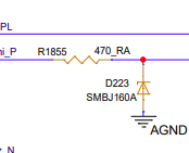
    • What is the point of the resistor + diode on only 1x pin per sensor? I copied one of them below for reference
    • How are you biasing the thermocouple? I don't see pull-up/pull-down resistors or anything else that biases the TC into the input range of the ADC. Check out our TC design for more info: https://www.ti.com/lit/pdf/sbaa274

    -Bryan

  • Hi Bryan,

    Thank you again for your helpful feedback on the schematic.

    I had a couple of quick follow-up questions based on your comments:

    1. For D232 (the BAS70 diode on the IDAC pin), you mentioned using a current-limiting resistor instead. Could you please suggest a suitable resistor value to replace the diode, assuming a 1 mA excitation current?

    2. Regarding the combination of R1855 (470 Ω) and D223 (SMBJ160A) on the RTD_1_Uhi_P line — these were added to provide input protection for the analog input. Do you see any specific issues or concerns with using these two components together in this context?

    Since I'm using only basic SPI communication with the MCU, I assume the START/SYNC and other auxiliary pins are not required.

    Thanks for your continued guidance and support.

    Best regards,
    Manikandan V

  • Hi Manikandan Velayudham,

    I would start with 1kohm for the resistor, but of course this depends on how much overvoltage you need to protect against (you want to limit the current into the ADC pin to <<10mA as per the absolute max values). Ensure the IDAC compliance voltage is also met now that you will have a 1V drop across a 1k resistor using a 1mA excitation current

    The protection should be okay, I was just more curious why you only have protection on one of the analog input pins and not both / all

    -Bryan