This thread has been locked.

If you have a related question, please click the "Ask a related question" button in the top right corner. The newly created question will be automatically linked to this question.

ADS1299EEGFE-PDK: There is no signal when the electrode attached to skin with ADS1299

Part Number: ADS1299EEGFE-PDK
Other Parts Discussed in Thread: ADS1299

Tool/software:

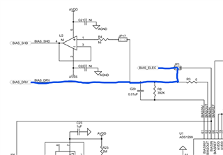
I am working on SPI communication between ADS1299 and nRF52840. I have an ADS1299EEGFE-DK board but I am not using the MMBO board. I established communication between ADS1299 and nRF52840 successfully. I can read and write in the register. When I try to gather signals from the ADS1299, I cannot get any signal. I am using dedicated bias and reference electrodes. I am using internal bias to drive. When I tap the electrodes, I can see the changes in the output, but when I connect the electrodes to the skin, there is no change. The register configuration I used and the hardware configurations are detailed below. Currently, I am working on one channel.

CONFIG1 -> 0xD6

CONFIG2 -> 0xC0

CONFIG3 -> 0xEC

CH1SET -> 0x60

MISC1 -> 0x20

JP2 -> 2-3 connected

JP20 -> 1-2 connected

JP24 -> 2-3 connected

JP25 -> 5th pin BIAS_ELEC

JP25 -> 6th pin REF_ELEC

JP25 -> 1-2 and 3-4 connected

JP1 -> 1-2 connected

JP6 -> 2-3 connected

JP7 -> 1-2 connected

JP8 -> 2-3 connected

  • Edited version:
    To read data, I am using this function. According to the status bits, it must return 0xC000. But when I try to read the stat_1 variable, it returns 0x00C0C0C0. 


    /** @brief Read Data Continuous Mode
        *
        *
        @details After RDATAC command received by ADS1299, it starts with RDATAC.
        Go over channel by channel and read values.
        @details This function returns channelData
    */
    void RDATAC_read_value(int32_t* channelData)
    {   
        new_data_available = false;
        uint32_t stat_1 = 0x00;
        static uint8_t dummy_message = 0x00; // __attribute__((aligned(4))) = 0x00;
        static uint8_t inByte;//        __attribute__((aligned(4)));
        //int32_t channelData[8];       // __attribute__((aligned(4))) = {0};
    
        nrf_gpio_pin_clear(CS_PIN);
    
        for(uint8_t i = 0; i < 3; i++)
        { 
          spi_transfer_byte(&dummy_message, &inByte, 1);
          stat_1 = (stat_1 << 8) | inByte;
        }
        
        for(uint8_t i = 0; i < 8; i++)
        { 
          for(uint8_t j = 0; j < 3; j++)
          {
            spi_transfer_byte(&dummy_message, &inByte, 1);
            channelData[i] = (channelData[i] << 8) | inByte;
          }
        }
        
        nrf_gpio_pin_set(CS_PIN);
        
        for (int i = 0; i < 8; i++) { // Convert 3-byte 2's complement to 4-byte 2's complement
            if ((channelData[i] >> 23) == 1) { // Check if bit 23 is 1 (negative number)
                channelData[i] |= 0xFF000000; // Sign-extend by setting upper 8 bits to 1
            } else {
                channelData[i] &= 0x00FFFFFF; // Clear upper 8 bits for positive number
            }
        }
    
        new_data_available = true;
    }
    

  • Hi Omer,

    Can you try configuring the channel to use the internal square wave test signal? This will validate your ADS1299 is operating normally and that your data transmission is correct.

    Please also refer to our ADS129x FAQ page for more suggestions:

    [FAQ] Common Questions for TI's ADS129x Family of Bio-Potential ADCs - Data converters forum - Data converters - TI E2E support forums 

    Regards,

    Ryan