This thread has been locked.

If you have a related question, please click the "Ask a related question" button in the top right corner. The newly created question will be automatically linked to this question.

ADC3562: tPD formula

Part Number: ADC3562

Tool/software:

Hi,

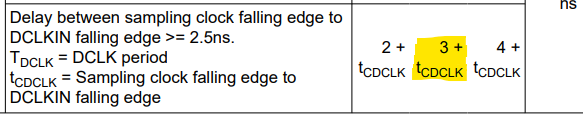
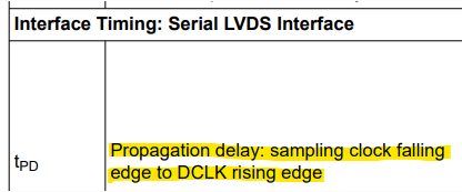
The datasheet of ADC3562 shows the formula to calculate tPD as shown in below.

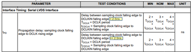
I think the formula should be 

 tPD = 3 + tCDCLK + TDCLK/2 (tCDCLK >= 2.5ns)

 tPD = 3 + TDCLK + tCDCLK + TDCLK/2 (tCDCLK < 2.5ns)

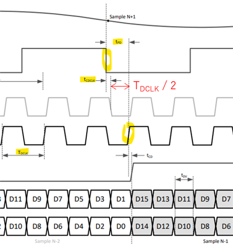
TDCLK / 2 should be added here.
Is my understanding correct?

PLS refer the following timing chart to understand it.

If my understanding correct, could you revise the datasheet to correct the formulas?

Best Regards, Taki

  • Hi Taki, 

    The datasheet specification table is correct. Tpd is not measured like the figure is showing. Tpd is the actual analog propagation delay in the device. That delay will change by one DCLK clock cycle depending on the relationship described in the test conditions. Thanks!

    Cheers,
    Fadi

  • Hi Fadi-san,

    I have a measurement result which was sent by my customer and it seems that the result is similar to the figure.
    I sent you the customer's result by mail.  Please discuss with me offline.

    Best Regards, Taki 

  • Hi Fadi-san,
    Thank you for your reply offline.  I will continue this discussion on this thread.
    We, my customer and I are still confusing, so that please let us confirm your answer. 

    Your point in your answer in above and in the mail is shown in below.
      - The explanation about Tpd in datasheet specification is correct and Tpd shown in figure 7.1 in the datasheet is not correct.
      - Tpd is defined as the portion of the full device latency that will not change across sample rates.

    Based on your answer, I looked into the table to understand the definition of tPD and found a difference in two portions in the table.  

    1. According to the table, tPD is about the time from sampling clock falling edge to DCLKIN falling edge.
         

    2. On the other hands, the definition of tPD is propagation delay : sampling clock falling edge to DCLK rising edge.
          

    The end point of time period for tPD is around DCLKIN falling edge in case "1" in above and DCLK rising edge in case "2".
    Which is correct, case "1" or "2" for tPD definition?

    Where, "2" in above and Figure 7.1 is saying same things, so that I expect "1" is correct.  

    Best Regards, Taki

  • Taki-san,

    For #1, t_CDCLK is just a delay between the input DCLKIN and sampling clock. This delay is not related to the device but it will be dependent on the customer setup. This is indicating that the t_pd will change based on the relationship of DLCKIN and CLK (it is recommended that DCLKIN and CLK should be sourced from a common reference so their phase relationship is not constantly changing). This has nothing to do with the definition of t_pd.

    For #2, there is some nuance. In a single clock latency device, you can, in theory, measure the t_pd from the falling edge of the sampling clock to the rising of DCLK that indicates it is the sample you are interested in. Note, if the device latency is higher than 1 clock cycle then this will be the t_pd + number of clock cycles. Depending interface mode, the device latency will change: 

    Thanks!

    Cheers,
    Fadi

  • Fadi-san,

    I understood your comment for each of #1 and #2. 
    What is your conclusion for my question : Which is correct, #1 or #2?  

    Best Regards, Taki

  • Taki-san,

    #1 and #2 are different things. t_cdclk is not t_pd.

    Cheers,

    Fadi

  • Fadi-san,
    Thank you for your comment. 
    I understood there is an inconsistency between #1 and #2 in 6.8 Timing Requirement table" of the datasheet.

    #1 : t_pd = 3+t_cdclk
    #2 : t_pd is the time period between sampling clock down edge and DCLK up edge in the table of the datasheet.

    Which is correct, #1 or #2?

    Best Regards, Taki

  • Taki-san,

    There is no inconsistency...

    3+t_cdclk is the value you for the measurement

    #2 is defining the t_pd and #1 is given you the measured value.

    I understand it is confusing that the t_cdclk is being defined with falling edge to falling edge and the t_pd is defined as falling edge to rising edge. My point is that you shouldn't need to worry about this because the t_cdclk doesn't equal t_pd (if it did then this would be a problem). It is just how it has been specified.  

    Cheers,

    Fadi

  • Fadi-san,

    If #1 is correct, #2 should be "sampling clock down edge to DCLKIN down edge".

    If #2 is correct, #1 should be t_pd = 3 + t_cdclk + TDCLK/2. 

    Is my understanding wrong?  If so, PLS point it out.

    Best Regards, Taki