This thread has been locked.

If you have a related question, please click the "Ask a related question" button in the top right corner. The newly created question will be automatically linked to this question.

AMC60704: AMC60704's VDAC can't be set by the GUI

Part Number: AMC60704

Tool/software:

Hi there,

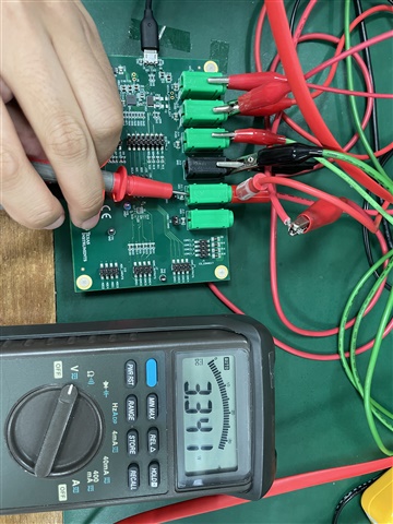
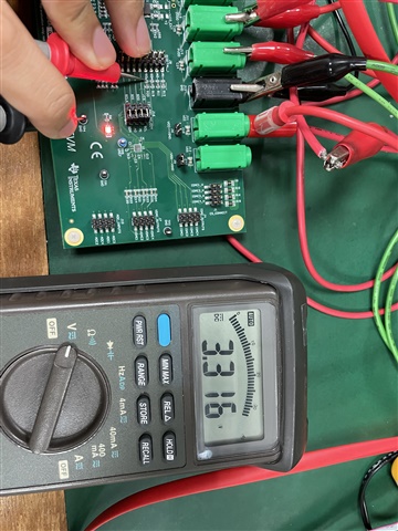
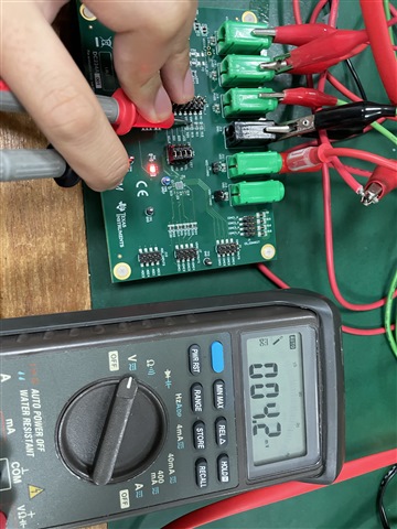
I'm using AMC60704EVM to generate the VDAC, but after setting the VDAC on GUI, I still unable to measure the voltage on VDAC pin.

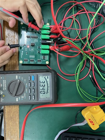
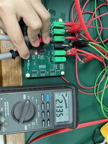
I appied 3.5V on VIO, VDD, VCC and 2.1V on PVDD, and didn't apply voltage on VSS.
I'm using I2C and A1,A0 = 11 (No connection on J8)


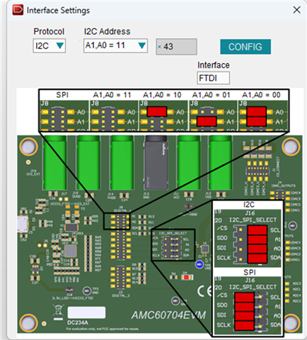
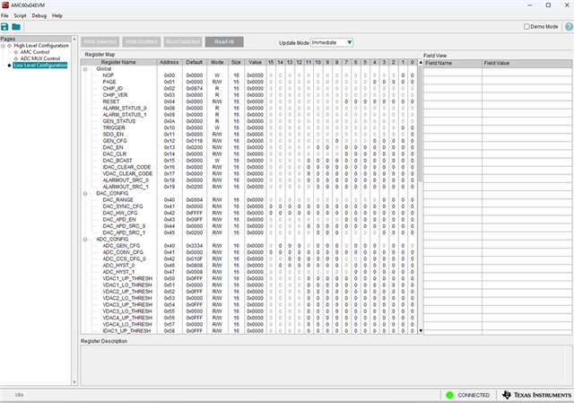
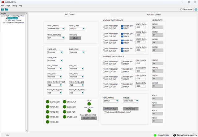
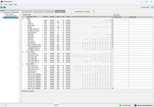
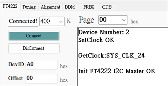
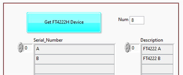
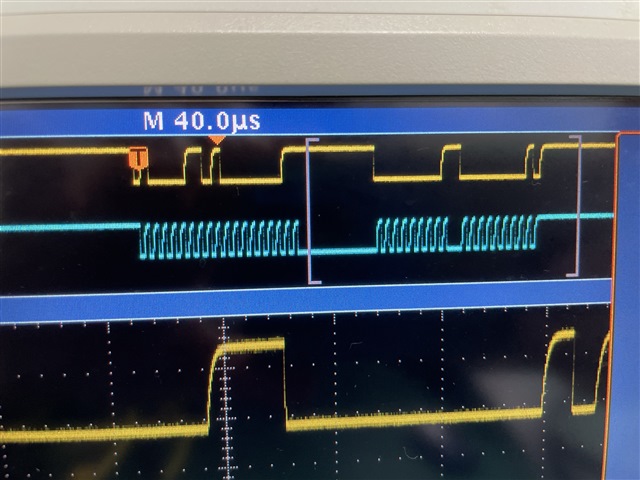
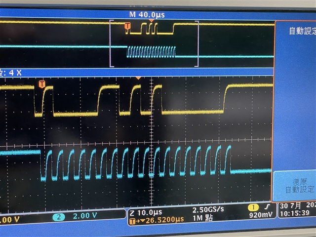
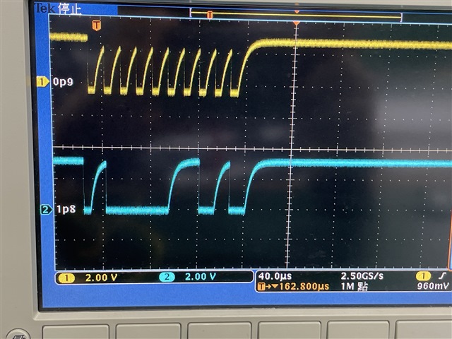
The GUI's screenshots are listed below. It's weird that after I clicking the READ ALL button, all values change to zero, I think the CHIP ID sould be read back at least. But the GUI shows connected (green light), so I think the connection between PC and FT4222 works. I click power_en and sync and set 0xfff for the VDAC output, and click LDAC, the VDAC pins are all measure 0v,  and the Vref pin measured as 0.684v, if I setup anything worng? Please help! Thanks!  

  • Hi Brendan, 

    Can you share a picture of the EVM so I can see the jumper settings? It does look like the EVM is not communicating with the GUI at all. 

    Usually, I2C returns 0xFF00 when reads are unsuccessful because the SDA line remains high. This could mean there is an issue with the GUI itself. Can you measure the I2C pins on the EVM and make sure the I2C commands are toggling on the SDA and SCL pins when you start a read or write command?

    Best,

    Katlynne Jones

  • The Jumpers remain the default setting 

    Belows are every Designator's Voltage

    VIO

    DVDD

    PVDD 

    VCC


    I2C's Voltage

    I measured it when I click Read All button

    SCL


    SDA

  • Hi Katlynne,
     

    It seems like the FT4222 lose the connection with GUI? Based on what you said about I2C's pins, I click the read write button but the SDA pin remains 4.2mV 

  • Hi Brenden, 

    SDA should be pulled up to VIO when no communication is active. Something in the system is pulling it down which is not expected. 

    Can you try using SPI mode? Move the corresponding jumpers on J16 to the left side to select the SPI signals. 

    Best,

    Katlynne Jones

  • After switching to SPI mode, I clicked the “Read All” button, and every value returned 1.
    I then measured the voltages:
    CS and SDO pins stayed at 3.3 V both before and after clicking “Read All.”
    SDI dropped from 3.3 V to 13.5 mV after the click.
    SCLK remained at 1.2 mV the whole time.
    Could the FT4222 or another component have been damaged?

  • Hi Brenden, 

    Make sure to enable the SDO pin in the GUI when reading using SPI. The SDO pin is disabled by default. I think the GUI does send a command to enable this on startup, but just in case also try sending the SDO enable command once before reading. 

    Usually if there is an issue with the GUI installation it will throw an error before opening, but I have seen once or twice where it will open but still not talk to the FT4222 chip. It is possible that the chip is damaged but I'm not entirely sure. One thing we can try is python code. Can you try running this example to read from the CHIP_ID register?  

    This code is pretty basic, but it should at least let us confirm if the issue is with the GUI installation or the FT4222 chip itself. 

    import ft4222
    import ft4222.I2CMaster
    import time
    from ft4222.GPIO import Dir, Port, Output
    
    # list devices
    nbDev = ft4222.createDeviceInfoList()
    for i in range(nbDev):
        print(ft4222.getDeviceInfoDetail(i, False))
    
    
    # dev = ft4222.openByDescription('FT4222 B')
    dev1 = ft4222.openByDescription('FT4222 A')
    dev1.i2cMaster_Init(100)
    ftdiGpioSession = ft4222.openByDescription('FT4222 B')
    ftdiGpioSession.setSuspendOut(False)
    ftdiGpioSession.setWakeUpInterrupt(False)
    
    ftdiGpioSession.gpio_Init(gpio2=ft4222.GPIO.Dir.OUTPUT, gpio3=ft4222.GPIO.Dir.OUTPUT)
    ftdiGpioSession.gpio_Write(ft4222.GPIO.Port.P2, True)
    
    def dataWriteList(number):
        strBin = str(bin(number)[2:])
        strBin = '0' * (((len(strBin) + 7) & - 8) - len(strBin)) + strBin
        writeList = []
    
        for i in range(len(strBin) // 8):
            writeList.append(int(strBin[i * 8: (i + 1) * 8], 2))
    
        if len(writeList) < 2:
            writeList.insert(0, 0)
    
        return writeList
    
    def i2cWrite(deviceAddress, regAddr, regData):
        dataArray = bytearray([int(regAddr)] + dataWriteList(int(regData)))
        dev1.i2cMaster_Write(addr=deviceAddress, data=dataArray)
    
    def i2cRead(deviceAddress, regAddr):
        dev1.i2cMaster_Write(addr=deviceAddress, data=int(regAddr))
        data = dev1.i2cMaster_Read(addr=deviceAddress, bytesToRead=2)
        int_val = int.from_bytes(data, 'big')
        return hex(int_val)
    
    
    #Example operations
    
    print('CHIP_ID', i2cRead(deviceAddress=0x43, regAddr=0x2))


    Best,

    Katlynne 

  • Hi Katlynne,

    Since after viewing that python code, I found that our company already had GUI have the same function as the code you provided, so I run these two GUI to read chip id from FT4222, based on the result, I believe the FT4222 works fine, maybe AMC60704 have been damaged? Thanks.


    Best,
    Brenden

  • Hi Brenden, 

    The best way to confirm that the FTDI controller is working is to remove all connections to the device (remove jumpers on J16) and measure the I2C or SPI signals on a scope to ensure they are actually toggling out with the commands from wither the GUI or python code. It's hard to verify this with a voltmeter as the I2C signals are pretty fast. 

    If you confirm that you see the signals, then I would agree that the AMC60704 is the problem and is not responding to communication. 

    Best,

    Katlynne Jones

  • Hi Katlynne,

    After removing all jumpers on J16, the I2C signal correctly been measured by the scope.

    Below was the waveform after clicking "Read All" button.


    Below was the waveform after clicking "LDAC" button.


    If I didn't remove those jumpers, the waveform cannot be measured.

    I removed the power supply jumper for FT4222 (J18) and use the development board to send the I2C command directly to AMC60704 and found that the AMC60704 didn't ACK, so based on these measured results, I believe the AMC60704 was damaged. 


    I wonder if we can get another EVM? Since we'll use this chip in our future product development, I need to verify if AMC60704 able to work well in our circuit. Thank you!

    Best,

    Brenden

  • Here's the info of the EVM.


  • Hi Brenden, 

    I agree, the issue seems to be with the device. I've just sent you an email for more details. 

    Best,

    Katlynne Jones