ADS8339EVM-PDK: Conversion data when Data Rate / SCLK is changed

Part Number: ADS8339EVM-PDK
Other Parts Discussed in Thread: ADCPRO, ADS8339

Tool/software:

Hello

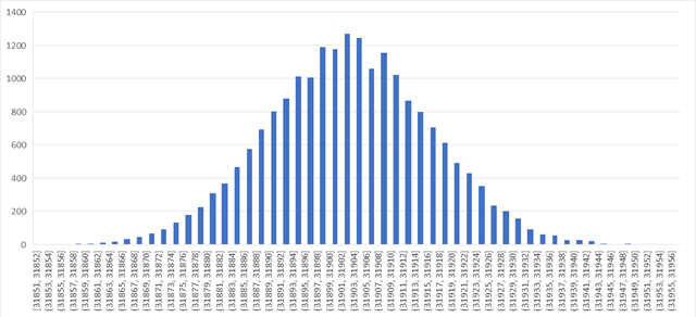
When DC is applied to the ADS8339EVM-PDK evaluation board, the conversion data changes depending on the settings.

Since the DC voltage contains noise from electronic circuits, the converted data is expected to be normally distributed.

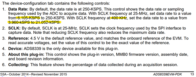
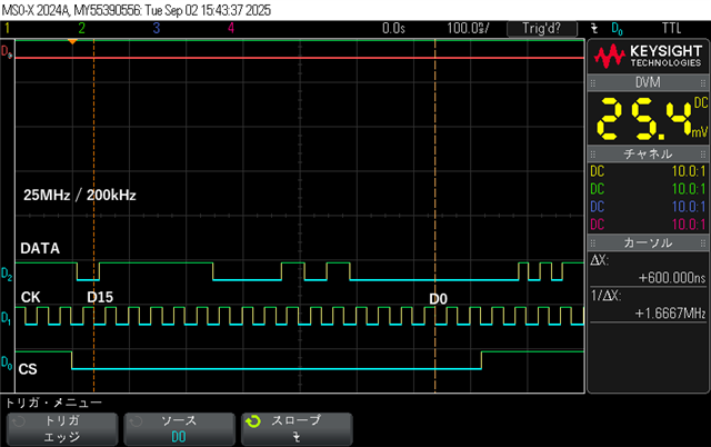
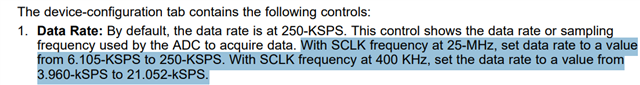
Data Rate 250kHz / SCLK 25MHz

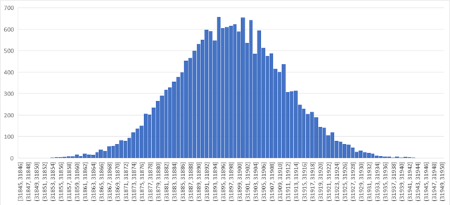
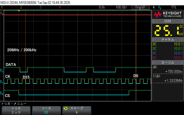
Data Rate 5kHz / SCLK 5MHz

Why does this happen when changing settings while the input signal remains the same?

  • Hi Furusawa-san,

    Thanks for your question. Apologies for the delay as I was out of office.

    Since you are using the EVM, I am wondering if this is a GUI issue. Could you try using 400kHz SCLK when setting the data rate to 5kHz?

    Best regards,

    Samiha

  • Hello, thank you for your answer.

    I got the conversion data with SCLK 400kHz / Data Rate 5kHz.

    I'm getting more and more confused.

  • Hi Furusawa-san,

    Thank you for sharing. Could you send me the raw .csv/excel files? I am wondering if this is a binning issue.

    Best regards,

    Samiha

  • Hello

    I will send you the data file.

    20250730_ADS8339.zip

  • Hi Furusawa-san,

    Looking at your files for data rates less than 250ksps, it looks like the LSB is stuck at 1 in one case, and LSB and LSB+1 are both stuck in another case. I think this is a missing code issue. It could also be a software issue but I can't say with certainty. The datasheet does say that this device does not show missing codes, but it was thoroughly tested at only 250ksps. I will look into ordering an EVM and looking into this further, but it will take some time.

    Best regards,

    Samiha

  • Hello.
    I understand.

    I'm not in a hurry, but I'd like some kind of answer.

    Thank you.

  • Hi Furusawa-san,

    My test EVM arrived. Could you share if you made any changes to your EVM and if you are using any input for this histogram analysis? Are you grounding the inputs or leaving them floating? Also, could you share a screenshot of the ADCPro GUI settings you are using?

    Also, may I ask if this is a device you are evaluating for use or if this is a mature design? What kind of application is this for?

    Thank you!

    Best regards,

    Samiha

  • Hello

    I haven't made any changes to the evaluation board.

    The input is connected to the oscillator.
    For this evaluation, it is set to 0[V] in DC mode.

    Data and screenshots of when connected to oscillator (OSC), no connection (N.C.), and ground (GND) are sent.

    A product using the ADS8339 has been developed and is scheduled for mass production.
    The application is sensor conversion.
    There were problems with the behavior of the prototype, so an evaluation board was used for evaluation.

    Thank you.20250806_ADS8339.zip

  • Hi Furusawa-san,

    Thanks for your response. I will try this out and get back to you.

    Best regards,

    Samiha

  • Hello

    It seems that lowering SCLK shortens CS.

    There is no problem at 25MHz.

    At 20MHz, CS returns before the 16th bit of the clock.

    Is this normal?

  • Hi Furusawa-san,

    Thanks for sharing. I've been seeing something similar in my testing. I believe this EVM and software may have been designed for use only at 25MHz. I noticed at different SCLK frequencies apart from these two, the CS does sometimes rise before the full 16 clocks. However, if I use larger values of SCLK, like 22 or 24 MHz, with 200kHz sampling, I do see 16 SCLKs. I think this software is not setup to optimize for different SCLKs vs data rates.

    I think the reason you are seeing missing codes in your histogram at SCLK = 5MHz is due to CS rising prematurely, as we are seeing in your 20MHz SCLK screenshot. Evaluation of variable SCLK (apart from 25MHz) must not have been considered at the time it was made. I'll go ahead and work on updating the user's guide to clarify this point. I hope this helps.

    *On further testing, this GUI software code seems to not be able to support lower SCLK/data rate values. This is a software limitation. The ADC itself is able to support SCLKs and data rates as specified in the datasheet.

    Best regards,

    Samiha

  • Hello

    Is it possible to fix the software so that it works properly at 5MHz/5kHz?

  • Hi Furusawa-san,

    Unfortunately, this is not possible as a different development team (no longer available) worked on that software. The ADC does work at 5MHz SCLK and 5kHz data rate. While the GUI does not support it, we have tested ADC timing functionality for this case using MSPM0 MCU code. May I ask what the goal of your testing is? Are you checking particular specs at 5MHz/5kHz or just timing feasibility? If you are able to verify functionality at 5MHz/5kHz, will you move on to schematic design?

    We do have some c code available for a similar ADC that can be repurposed for this ADC: https://www.ti.com/tool/download/ADS7066-C-EXAMPLE-CODE

    Best regards,

    Samiha