This thread has been locked.

If you have a related question, please click the "Ask a related question" button in the top right corner. The newly created question will be automatically linked to this question.

ADS127L21: Daisy-Chain Connection

Part Number: ADS127L21
Other Parts Discussed in Thread: ADS127L11

Tool/software:

Hello,

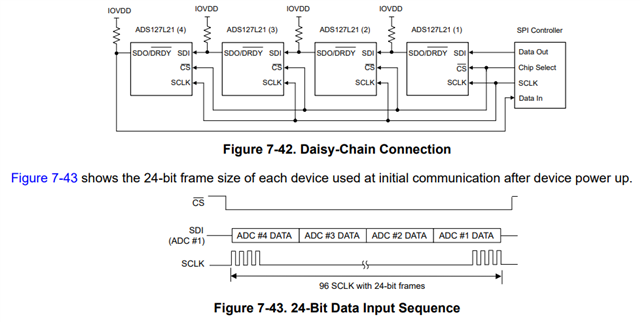
in the datasheet of the ADS127L21 a daisy-chain connection is described in a schematic using four ADCs. There is the demand: "Program the SDO/DRDY pin to data-output-only mode." 

In the "FILTER3 Register" you can program the "Data output pin function selection". This register has the value 01hex after reset, which means: "SDO/DRDY is a dual mode: Data output and data ready". This register must be programmed to 00hex to get "SDO/DRDY pin is data-output only mode".

But my question is, how can I program the devices ADS127L21 in a daisy-chain connection, which have wrong programming for the SDO/DRDY pin after the reset?
I think, that this programming to “data-output-only mode” is necessary for correct working of the daisy-chain.

But after a reset, which is performed after switching on the supply voltages, this pin has wrong programming, and the daisy-chain doesn't work. So, it is impossible to program the ADCs.

There is a contradiction.

For the ADS127L11 you can read at the same part of the datasheet: "The SDO/DRDY pin must be programmed to data output-only mode." This demand is even stronger.

 Perhaps you can explain me, how the programming of the ADCs for this SDO/DRDY pin works in daisy-chain connection.


Best regards,
Friedrich


  • Hello Friedrich,

    So, the ADS127L11 defaults to SDO only mode, which is convenient when using daisy-chain; a bit of a problem for the ADS127L21 that defaults to dual SDO/DRDY mode.

    You can always write to the first ADC in the daisy-chain regardless of the SDO mode; the dual mode corrupts the data for the rest of the devices in the chain.  

    This sequence should work after reset:

    Write 0x00 to FILTER3 register for all ADCs in the chain.

    /CS low: start frame

    0x008B00 008B00 008B00 008B00 :   96b frame for 4 ADCs in daisy-chain

    /CS high; end frame

    Repeat frame for number of ADCs in chain; 4

    After the first pass, Device 1 will be configured correctly, after second pass, Device 1 and 2 will be configured correctly, and so forth.

    I have not actually tried this, so please let me know if this works.

    Regards,
    Keith Nicholas
    Precision ADC Applications

  • Hello Keith,

    thank you for your answer!

    If the wrong programming of the SDO/DRDY pin of the first ADC in the daisy chain corrupts the data of the other ADCs in the daisy-chain, this can be a problem, because I don’t know, what happens with this further ADCs, which can be programmed to not desired states.

    I have studied the datasheet of the ADS127L21 again and again and got the result, that it doesn’t matter, what programming of the SDO/DRDY pin is used.
    The reason is as follows:

    The daisy-chain of the ADCs is a large shift register, which transfers the serial bits (data at SDI) at the falling edge of the SCLK. If I look at the signal at SDO/DRDY pin in figure 7-41, then I see, that at the falling edges of the SCLK there is never the DRDY signal. Therefore, the DRDY signal on the SDO/DRDY pin can never have any influence on the shifted data to the next ADC.

    In my opinion it doesn’t matter, what value has the DATA_MODE in Filter3 Register. The daisy-chain works in any programming of the SDO/DRDY pin.

    I have no hardware to check it.
    Now, I’m only planning a new hardware.

    Best regards,
    Friedrich

  • Hi Friedrich,

    I am going to take a closer look at this; I had assumed you already had hardware setup.  Please give me until end-of-business on Friday to follow-up.

    Thanks,
    Keith

  • Hi Friedrich,

    I worked on this in the lab.  After reset (either power-up or asserting the /RESET pin), as long as the START pin is kept low, then the DRDY signal will remain high after the required /RESET delay td-RSSC (10000 CLKIN periods).  The ADS127L21 will treat an 0xFFFFFF input on the SDI pin as a No-Operation (NOP).  In this case, all ADCs in the daisy-chain will either see the intended command data, or will interpret the input as a NOP.  This will allow writing to the FILTER3 register to configure the SDO/DRDY pin as SDO only.  You will need to repeat the entire SPI frame equal to the number of devices in the daisy-chain, so that each ADC is configured in SDO only mode.

    Below is the output of the first ADS127L21 in a string of ADCs.  You can see on the first frame, the output is 0x000000h followed by 0xFFFFFFh.  The first 24bits are 0 since the ADC has not performed any conversions after RESET.  Then the SDO pin follows the high output of the /DRDY signal.  After /CS is taken high, the first ADC then reconfigures the SDO/DRDY pin for SDO-only, and in the second frame, we now see 0x000000h followed by the correct command for the next ADC in the chain, 0x008B00h.

    After properly configuring each of the ADC FILTER3 DATA_MODE bits to 0x00b, you can then further configure the device and start taking conversion readings by either setting the START pin high, or writing to the START bit in each of the ADCs.

    Regards,
    Keith

  • Hello Keith,

    thank you very much for this precise answer!

    My theoretical thinking was wrong. It's now clear to me that the daisy-chain works only with programming DATA_MODE in Filter3 Register to 00b (
    SDO/DRDY pin is data-output only mode).
    You have described the successful programming of the daisy-chain and it isn’t easy for the ADS127L21.

    Best regards,
    Friedrich