This thread has been locked.

If you have a related question, please click the "Ask a related question" button in the top right corner. The newly created question will be automatically linked to this question.

ADS8504: Temperature drift

Part Number: ADS8504

Tool/software:

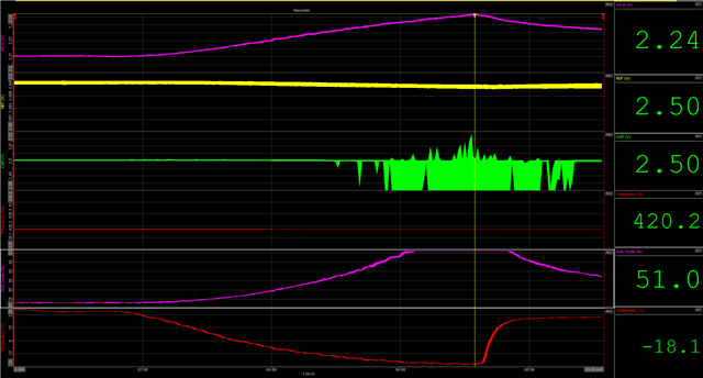
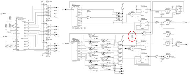
I use the the ADS8504 to control a shift register which in turn control the gates of a couple of transistors to change the binary code of a binary counter. All this to get a square vawe output with a frequency that shifts with the input voltage of the AD. When combined with a fixed frequency I get a PWM signal with 420Hz frequency and ~5-50% duty cycle. I have got this to work as intended but when I test the design in a temperature chamber the duty cycle drifts even when the input is tied to a fixed voltage of 2.2V. It is stable from 0C to +100C. But when going below 0C the output starts to drift. See the pictures below.

Any idea why this happens or what causes this?

 Schematic

Data log

// Robert

  • Hi Robert,

    Welcome to our e2e forum!  How much drift are you seeing?  I looked at the datalog, but I have no idea what those signals are or how to interpret the traces shown. There is some text on the left side, but it is not readable for me.  Are you able to monitor the REF and CAP pins?  Do you see drift on either of those nodes?

  • I will try to add the image of the data log directly. The top graph shows the input voltage to the AD. It is 2.2V and generated with a 1k resistor and a zener diode. 2nd graph is an output voltage which has nothing to do with the AD measurements. 3rd graph is the temperature in the chamber, going from +20C to -20C. 4th graph shows the output frequency of the PWM. Last graph shows the duty cycle of the PWM output, that is were the drift occur, and I can't see any other part than the AD affecting that.

    I will try to measure the REF and CAP pins as well.

    // Robert

  • So I ran a test and monitored REF and CAP. They seem to be stable. I think the glitches on the CAP voltage is due to a bad connection to the probe. 

  • OK - scale factors might be playing a role here...

    The yellow trace does seem to have a slight downward bow, peaking right around your cursor, which is at the peak of your Vin.  If the reference drifts, the output will as well.  Are you able to pull the actual voltage levels off of VREF and compare that with Vin versus the raw ADC code outputs?

  • The dip in the Vref is like 4mV, would that really have that impact on the ouput? I mean 2.2V in is roughly 22% dutycycle and 5V is about 50% duty cycle. Would a 4mV change on the reference result in more than a 100% increase of the output?

    It is "easy" to do a raw code measurement on an oscillioscope, but that doesn't work over time. The measurements above is done with Dewesoft and even though I think it has 16 digital channel capability I beleive I only have hardware for 6 or 8 channels. So I could record the 6-8 MSB but I am certain it would show the same result as above. The parallel outputs is drifting.

  • Hi Robert,

    4mV is basically one LSB, so no - that should not have a large increase in your duty cycle.  By the same token, if the duty cycle is going from 22% to 50%, that would be a drift equal to a little over 2.79V.  The input range of the ADS8504 is +/-10V.  With the 2.5V internal reference, each LSB is ~4.8mV.  The 2.2V in should be giving you an output code of ~ 0x1C2.  A 5V input should get you into the 0x3FF range.  Not sure how easy it is for you to monitor the output of D9 to see if that is really flipping or not.  Curious to know; where R8 - R11 (the Q outputs of IC302 and IC304) go in your schematic?

  • I have been measuring different things all day long and the output from the AD was pretty stable, it only drifted like 4 bits or so. But I finally found the problem. The reset input on IC405 was floating due to the D403 diode. I just put a 10k pull-down resistor on the input and now everything works perfect.

    Thank you for the support even though it was all my fault.

    // Robert

  • Cool beans!

    Thank you for letting me know.